Sheet Metal Stamping and Forming
Have you ever wondered how metal products are made? From cars to household appliances, there are many items that are made from sheet metal. The process that is used to create these products is called sheet metal stamping or forming.
Basic Concepts of Sheet Metal Stamping
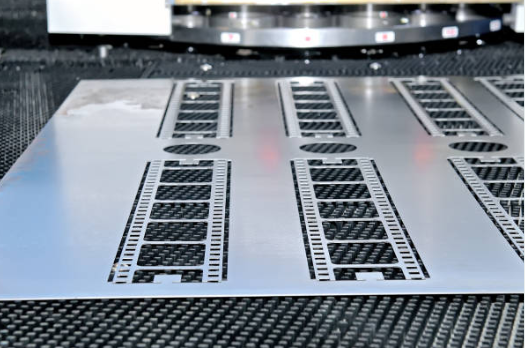
This traditional process uses a pair of matched solid dies to create a cavity where the sheet is placed. Different shaped parts require distinct dies. Sometimes multiple sets of dies are needed to form a complex sheet metal part. Designing and manufacturing these dies is expensive and depends heavily on the expertise of designers and workers. Additionally, conventional sheet-forming die tools take a long time to produce and require substantial storage space when not in use.
So what is sheet metal stamping?
Sheet metal Forming is a metalworking process that involves using dies to reshape flat sheets of metal into various shapes. Sheet metal stamping is a manufacturing process that is widely used in different industries. A press is used for most sheet metal forming processes, but high-energy rate forming and spinning can also be used to form sheet metals.
Parts produced by metal forming generally exhibit superior mechanical and metallurgical properties and reliability compared to those made by casting or machining. Metal forming is broadly categorized into two major subdivisions: massive forming operations and sheet metal forming processes.
What is the sheet metal forming process?
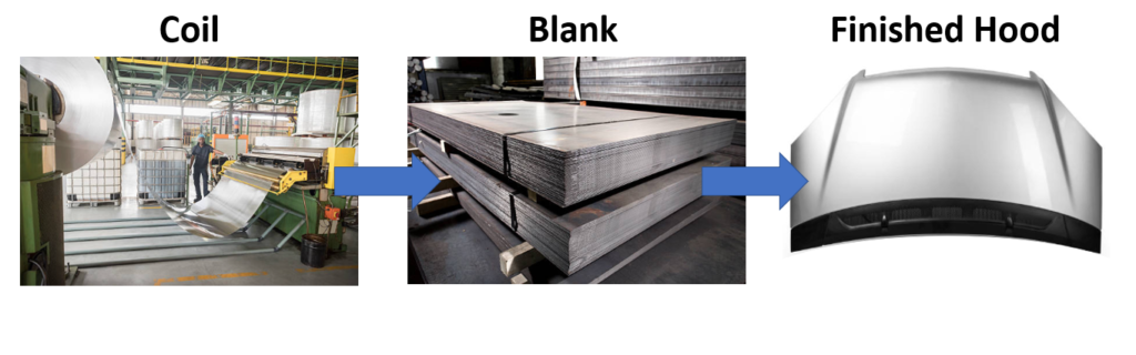
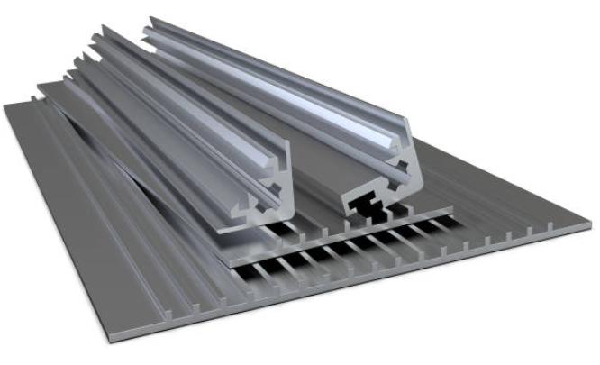
Sheet metal is a thin and flat piece of metal that can be easily cut and formed into different shapes. Sheet metal is usually provided in coils or in wide strips of cold or hot rolled steel. However, it is more typical for sheet metals to be cold-formed.
Sheet metal forming is a process that involves cutting, bending, and shaping metal. All metal alloys that possess ductility are suitable for this metalworking applications such as stainless steel, aluminum, copper, and brass. The plasticity of these metals makes it possible to deform them without losing the structural integrity of the metal.
Certain alloys, under the right conditions, can experience exceptional tensile deformation (up to 300%) without breaking. This capability has given rise to a specialized type of sheet metal forming known as “superplastic forming”. This technique is often used in conjunction with diffusion bonding to create complex aircraft frames and shapes. A variety of engineering materials can demonstrate superplasticity. Some of these include aluminum, titanium, and nickel alloys, certain steels, and even a few ceramics.
What’s the difference between bulk deformation and sheet metal forming
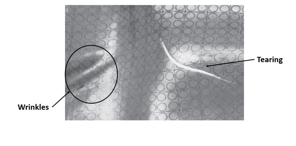
The key difference between bulk deformation and sheet metal forming is that in sheet metal forming the deformation mode is predominantly tensile and the area-to-volume ratio is high. Whereas in bulk forming (forging, extrusion, and rolling) the deformation mode is predominantly compressive and the work parts have a low area to volume ratio. In sheet forming, one or both of the deforming surfaces are often not supported by a tool. Failure in sheet forming is due to localized necking or wrinkling (buckling) rather than just fracture.
Sheet Metal Stamping Process
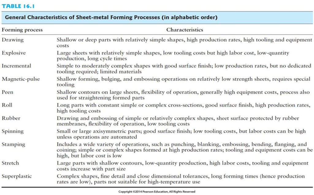
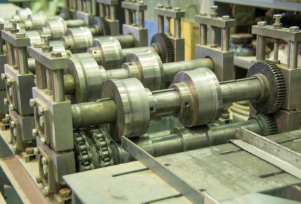
Next, let’s dive into the sheet metal stamping process. There are different types of sheet metal stamping processes, including progressive stamping, transfer stamping, and compound stamping. The steps of the sheet metal stamping process include blanking, piercing, bending, drawing, and flanging. Blanking involves cutting the metal into a specific shape, while piercing involves creating holes in the metal. Bending involves changing the shape of the metal, while drawing involves pulling the metal into a shape using a die. Flanging involves folding the metal into a specific shape. The equipment used in sheet metal stamping includes stamping presses, dies, and other specialized machines. Below is a full list of forming processes with characteristics.
What are the different types of deformation in sheet metal?
The deformation conditions in the sheet-forming processes are forming under:
- Shearing conditions (blanking)
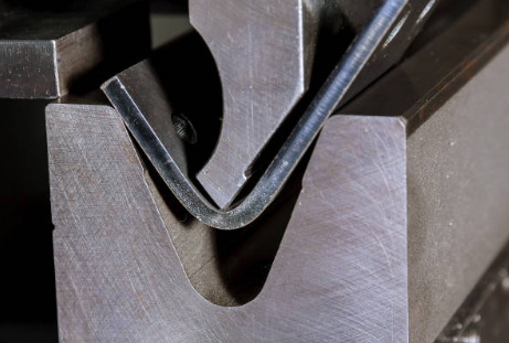
- Bending conditions
- Tensile and compressive conditions (deep drawing, spinning, flanging)
- Forming tensile conditions (stretching)
Advantages of Sheet Metal Stamping
Sheet metal stamping has many advantages, including precision and accuracy, cost-effectiveness, versatility, and quality control. It allows manufacturers to produce metal products with high levels of precision and accuracy, while also being cost-effective. The versatility of sheet metal stamping allows manufacturers to create products in various shapes and sizes. Quality control is also an essential aspect of sheet metal stamping. It allows manufacturers to ensure that their products meet specific standards.
What is meant by tailor-welded blanks?
Forming sheet metal into complex shapes is a crucial process. Typically, final sheet metal products consist of two or more blanks joined together. Traditional press tool-based forming is not practical for large or irregularly shaped products. Such as those used in defense, aerospace, shipbuilding, and railroad transportation. The costs associated with tooling, die-punches, and molds limit the feasibility of shaping large or irregular sheet metal parts using conventional press tools.

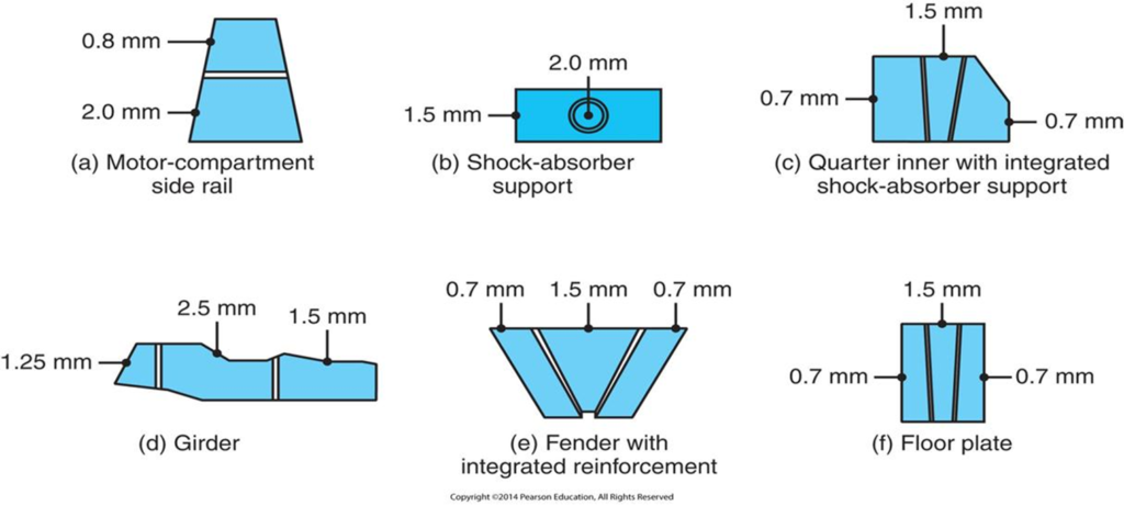
As a result, Tailor-welded blanks (TWBs) are a type of sheet metal that is created by two or more separate pieces of flat sheet metal of dissimilar thickness, and/or mechanical properties, joined together before forming to provide customized and superior qualities in the finished stamping. The individual sheets are welded together along a common edge. This creates a single sheet that has different material properties in different regions.
This also allows for the production of parts that have customized properties in different regions. As a result, this can lead to significant weight savings and improved performance. However a drawback is that the weld zone in sheet metal can act as a weak point, potentially leading to failures and defects.
What are the applications of tailor-welded blanks?
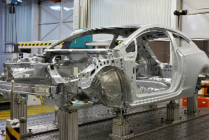
Tailor-welded products are primarily used in the automotive industry. Some components that use tailor-welded blanks are body side outer panels, front motor compartment side rails, and floor plates (floor pans). By using TWBs, automakers can reduce the mass of the vehicle while maintaining strength and stiffness in critical areas.
The advantages of using TWBs include:
- Weight reduction: By using TWBs, it is possible to create parts that are lighter than traditional parts made from a single material thickness. This can lead to significant weight savings and improved fuel efficiency/ range.
- Improved performance: By tailoring the properties of the material in different regions, it is possible to improve the performance of the part, such as by increasing stiffness or reducing vibration.
- Reduced manufacturing costs: TWBs can be produced using various welding methods, including laser welding and resistance welding, which can be more cost-effective than traditional forming methods.
In summary, tailor-welded blanks are a type of sheet metal that is created by welding two or more different types of sheet metal together. TWBs have a wide range of applications in industries such as automotive and aerospace. They offer advantages such as weight reduction, improved performance, and reduced manufacturing costs.
Applications of Sheet Metal Stamping
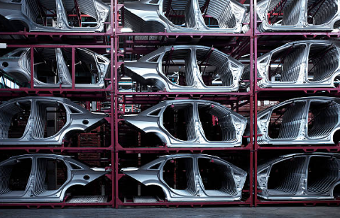
Sheet metal stamping is used in various industries, including the automotive industry, aerospace industry, electronics industry, and medical industry. In the automotive industry, sheet metal stamping are used to create most of the body-in-white parts. The aerospace industry, sheet metal stamping is used to manufacture airplane parts such as wings and fuselage. In the electronics industry, sheet metal stamping is used to create parts for computers, phones, and other electronic devices.
What are the defects of sheet forming?
Sheet metal forming is a complex process that involves the application of forces and deformations to a sheet of metal to create a desired shape. During this process, several defects can occur that can impact the quality of the final product. Some common defects of sheet metal forming include:
- Formability limits (tearing/cracks, necking, and spring back)
- Product appearance (wrinkling)
- Textures (anisotropy)
What is local necking in sheet metal stamping?
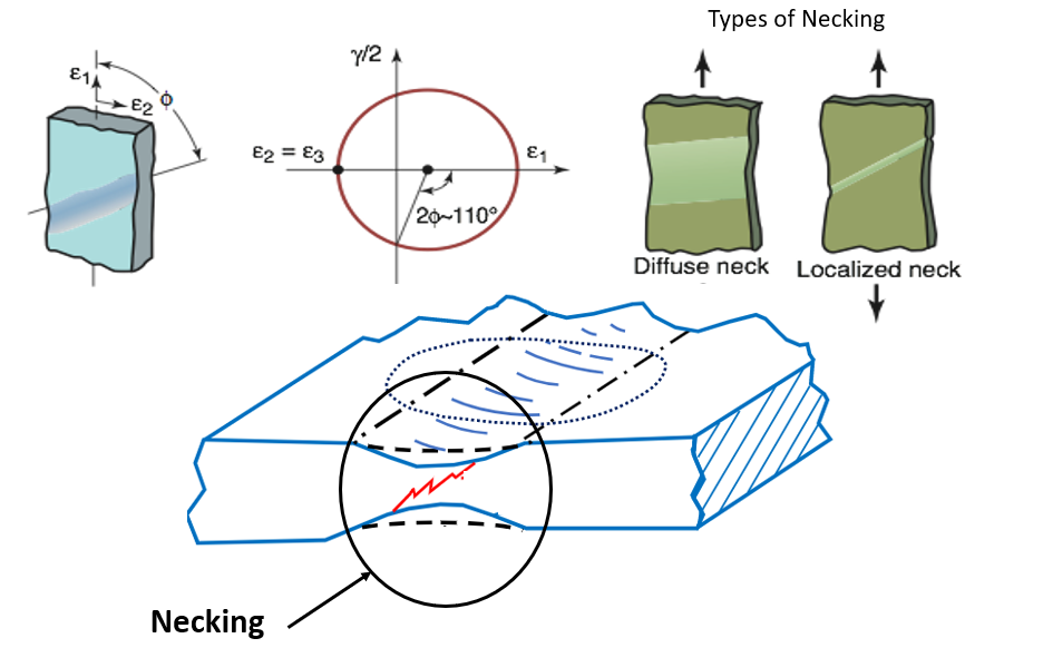
Local necking is a defect that occurs in sheet metal forming when the material undergoes excessive deformation/thinning in localized regions. This leads to an area in the work peice that is thinner than its surroundings resulting in a “neck”. This can occur in areas of the part where the curvature is high or where the material is constrained, such as at the edges of the die.
Local necking can lead to a reduction in strength and stiffness in the affected region. As well as an increase in the likelihood of cracking or tearing. To prevent local necking, several approaches can be used. For example adjusting the tooling design or the lubrication of the material to reduce the coefficient of friction between the material and the die. The angle of the neck can be determined by using Mohr’s circle for strain.
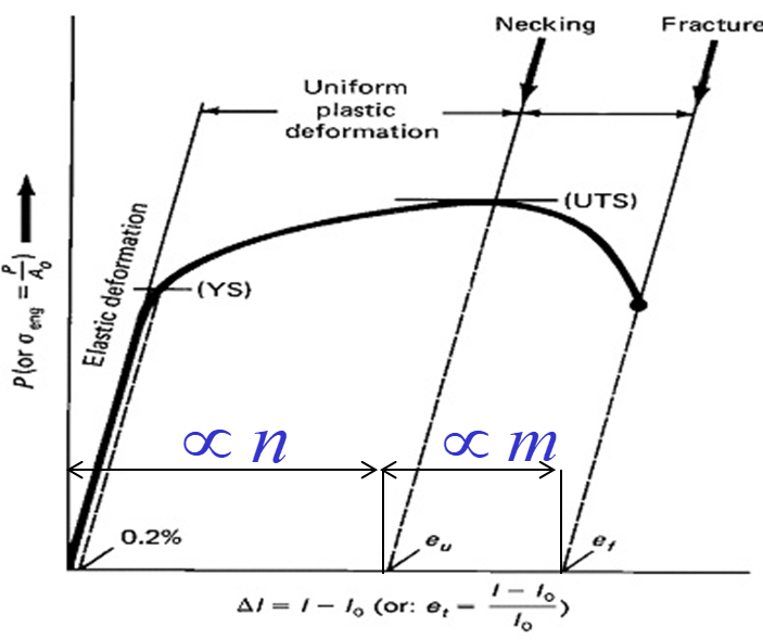
Effects of n and m values
Sheet metal properties relating to ductility are limited by necking and fracture. Here, n (strain hardening exponent) is proportional to the uniform deformation whereas m (strain rate sensitivity) is proportional to post-necking deformation. Both ‘m’ and ‘n’ reflect the total formability of the sheet metal.
Textures (Anisotropy) during sheet metal stamping
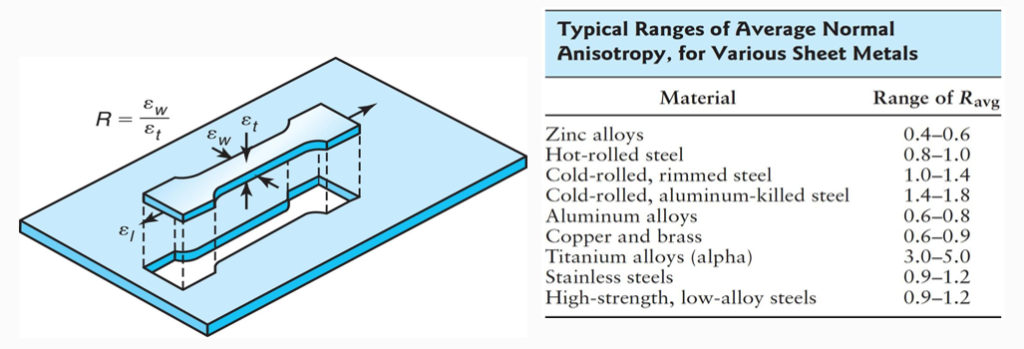
Anisotropy in sheet metal refers to the directional variation (directional properties) in a material’s mechanical properties, such as strength, ductility, and stiffness. Anisotropy can occur due to the inherent crystal structure of the metals. As well as any processing or forming that has been performed on the material. In deep drawing, anisotropy can have a significant impact on the final product. This directionality or anisotropy of properties is evident in a variation of Young’s modulus (E), yield strength (YS), tensile strength (TS), elongation, and other properties. In sheet forming, the relative magnitudes of strains also change during deformation due to texture.
What is the strain for anisotropic?
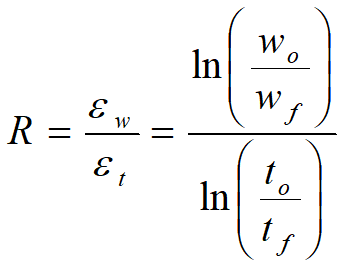
The strain for anisotropic sheet metal refers to the amount of deformation that occurs in a specific direction relative to the material’s anisotropy. In other words, anisotropic sheet metal will deform differently depending on the direction of the applied force. It is important to remember the following equations when dealing with anisotropy:
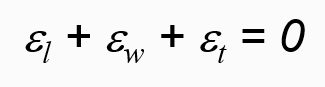
The volume of material remains constant (The sum of length, width, and thickness strain is equal to zero):
Normal Anisotropy:
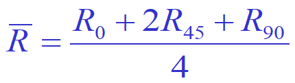
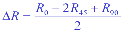
Average Anisotropy:
What does anisotropy of sheet in deep-drawing lead to?
The anisotropy of sheet metal in deep drawing can lead to several challenges, including:
- Wrinkling: Due to the non-uniform deformation characteristics of anisotropic sheet metal, it is more prone to wrinkling during the deep-drawing process. This can lead to defects and lower-quality parts.
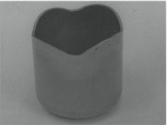
- Variations in material properties: Anisotropy can lead to variations in mechanical properties, such as strength and stiffness, in different directions. This strength difference results in uneven metal flow during deep drawing. For example, this can result in earing in a drawn steel cup (see picture below).
- Spring back: Anisotropic sheet metal is more likely to experience spring back, which is the tendency of a material to return to its original shape after deformation. This can result in parts that are not within the required tolerances or dimensions.
To overcome these challenges, several approaches can be used, including:
- Material selection: Choosing an engineering material that has minimal anisotropy can help to reduce the impact of anisotropy on the deep-drawing process.
- Tooling design: Tooling can be designed to compensate for the anisotropy of the sheet metal, such as by adjusting the draw bead geometry or adding additional flanges.
- Process optimization: Optimizing the deep-drawing process, such as by adjusting the feed rate or lubrication, can help to reduce the impact of anisotropy on the final product.
What is forming limit of sheet metal?
Sheet metal products are highly visible, therefore any mark/ localized thinning or texture of the sheet initiates during forming will result in a “bad” appearance which is highly undesirable. Examples include orange peel appearance and Lüder’s bands.
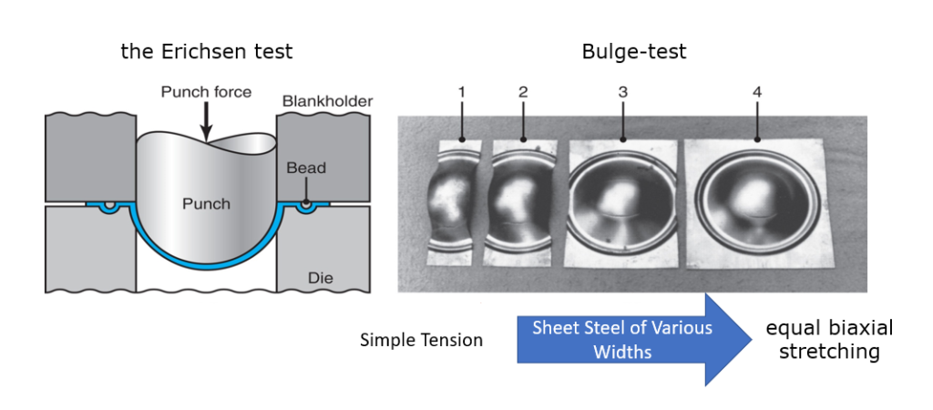
The forming limit of sheet metal is the maximum amount of deformation during the forming process that sheet metal can undergo before it ultimately splits and tears. This limit is determined by the properties of the material and the conditions of the forming process, such as the type of tooling, sheet metal gauge, and lubrication used during the forming process. Two common tests which can be conducted to test the forming limit of sheet metal is the cupping test (the Erichsen test) and the Bulge test.
What causes orange peel in metal?
Orange peel is what occurs when the sheet metal has undergone a large amount of deformation and as a result, becomes grainy in appearance. Large grain size in sheet metal results in this rough surface finish and surface texture.
What is springback in bending?
Springback is a phenomenon that occurs in sheet metal bending when the material angularly after being bent, returns partially or completely to its original shape once the external bending force is removed. This is due to the elastic recovery of the material and can lead to deviations from the desired final shape (usually the bend radius becomes larger). Springback is a common problem in sheet metal forming and can be influenced by several factors, including material properties, tooling design, and bending parameters. Under certain conditions, it is possible for the final bend angle to be smaller than the original angle (negative springback).

What is compensation for springback?
To compensate for springback, several approaches can be used. One approach is to overbend the part so that when the springback occurs, the part returns to the desired final shape. This approach requires experience and trial and error to and is usually carried out during the tool development phase to improve the part and tool quality. Another approach is to use a process called springback compensation, which involves adjusting the bending parameters or tooling design to account for the anticipated springback.
There are several methods for springback compensation, including:
- Pre-bending: This involves bending the material in the opposite direction of the final bend before performing the actual bend. This method can reduce the amount of springback but can also result in residual stress in the material.
- Air bending: This method involves bending the material without full contact with the die, allowing the material to springback more easily. The bending parameters can then be adjusted to compensate for the anticipated springback.
- Bottoming: This method involves forcing the material to contact the bottom of the die during bending, which can help to reduce springback.
- Design modifications: By making design modifications to the part, such as increasing the bend radius or adjusting the material thickness, the amount of springback can be reduced.
Overall, springback compensation is an important aspect of sheet metal bending to ensure that the final part meets the required specifications and tolerances. The appropriate compensation method will depend on the specific material and tooling used, as well as the desired final shape of the part.

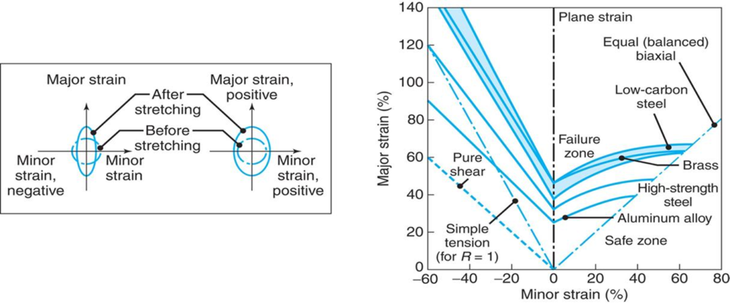
What is a forming limit diagram used for?
A forming limit diagram (FLD) also known as a forming limit curve is a graph that shows the forming limit of sheet metal as a function of the strain level and strain path. It is a useful tool for predicting the occurrence of defects, such as necking, tearing, and wrinkling (buckling), during the forming process. The FLD is created by performing a series of tests such as a punched dome test on the sheet metal material. The picture below shows an FLD for various sheet metals. It is important to remember that Although the major strain is always positive (stretching), the minor strain may be either positive or negative. R is the normal anisotropy of the sheet,
The FLD can be used in several ways, including:
- Process design: The FLD can be used to design the forming process by selecting the appropriate tooling and lubrication to ensure that the forming limit is not exceeded.
- Material selection: The FLD can be used to compare the forming limits of different sheet metal materials and select the one that is most suitable for the intended application.
- Quality control: The FLD can be used to monitor the forming process and detect any deviations from the expected forming limit, which can help to identify defects and improve the quality of the final product.
Sample Problem
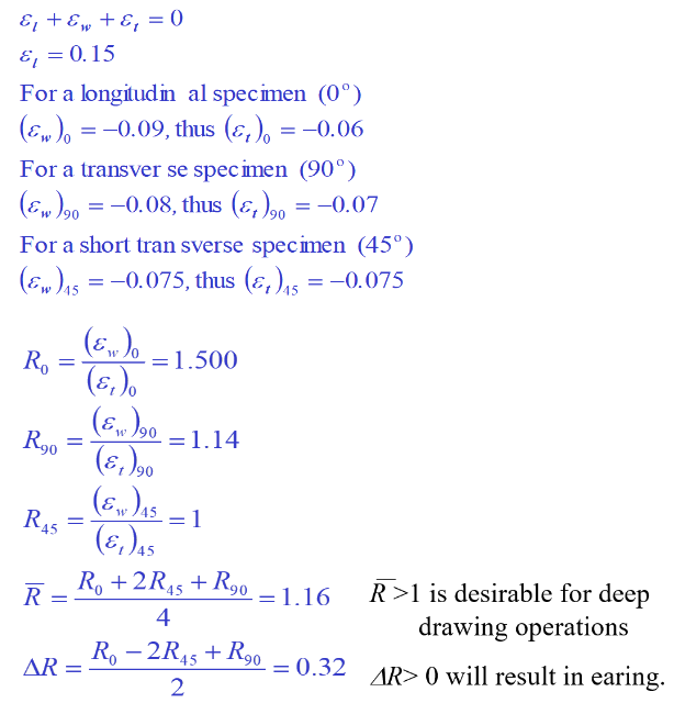
Uniaxial tensile test specimens were machined out of a metallic sheet with the loading axis parallel (0o), perpendicular (90o), and at 45o to the rolling direction of the sheet. The tests were stopped when the true strain reached 0.15 mm/mm. Measurements of the specimens showed the true width strain to be:
–(ew)0 = -0.090, (ew)90 = -0.080, and (ew)45 = -0.075
Discuss the effects of these results on the drawing behavior of the material.
Results
Conclusion
In conclusion, sheet metal stamping is a vital manufacturing process used to create a wide range of metal products. It involves cutting, bending, and shaping metal using specialized equipment and techniques. The process has many advantages, including precision and accuracy, cost-effectiveness, versatility, and quality control. It is used in various industries, including the automotive, aerospace, electronics, and medical industries. As technology continues to advance, sheet metal stamping will continue to be an essential manufacturing process in the future.


Itís hard to come by knowledgeable people about this subject, but you sound like you know what youíre talking about! Thanks