Mastering Sheet Metal Forming
Have you ever wondered about how sheet metal is formed to create everything from car parts to household appliances? Sheet metal forming is an essential manufacturing process that’s used in a wide range of industries.
In sheet forming operations, a thin sheet blank is plastically deformed into a three-dimensional object. This is done without significant changes in thickness or surface characteristics. Key features of sheet-metal forming include:
- The workpiece is a sheet or a part made from a sheet.
- Deformation usually causes substantial shape changes, but not changes in the cross-section of the sheet.
- The magnitudes of plastic and recoverable elastic deformations are comparable. With springback during elastic recovery is a significant control issue in the manufacturing process.
Examples of sheet forming processes include bending and straight flanging, surface contouring, linear contouring, deep recessing and flanging, and shallow recessing. Various techniques within these categories include bulging, dimpling, marforming, vacuum forming, and many others.
Fundamentals of Sheet Metal Forming
As science and technology have advanced, manufacturing methods and industry standards have undergone significant improvements. The techniques for shaping sheet metal components have evolved from the early days pre-Industrial Revolution. Before mass production, manufacturers used hand tools to strike the workpiece. The use of presses and metal dies during the Industrial Revolution enabled mass production. Sheet metal forming is now a highly efficient method for creating complex three-dimensional parts with minimal material waste.
What exactly is sheet metal?
Sheet metal is a flat-rolled engineering material typically made of metal alloys, such as steel or aluminum alloy. It comes in various thicknesses, also known as gauges. The thickness of sheet metal can range from ultra-thin foils just a fraction of a millimeter thick to thick plates several millimeters thick, depending on the application. Sheet metal is characterized by its mechanical properties. Such as its malleability, ductility, and strength, which make it ideal for forming into different shapes.
What are sheet metal forming processes?
Sheet metal forming involves shaping and cutting metal sheets to create various components. This process transforms metal sheets into the desired shapes and forms. When it comes to sheet metal forming, it’s crucial to understand the basic concepts. The key concepts are:
- Shearing involves cutting or trimming the sheet metal to achieve the desired shape/ removing excess material.
- Bending involves using tools such as press brakes or hand brakes to bend the sheet metal along a straight or curved line. This technique is commonly used to create parts such as brackets, flanges, and boxes.
- Stretching involves deforming the sheet metal to create a shape or cavity.
Understanding these fundamentals is essential to grasping the different techniques used in sheet metal forming.
What is shearing in sheet metal?
Shearing in sheet metal is the process of cutting or separating the sheet metal along a straight line. The shearing process involves applying a shearing force to the sheet metal. This causes the workpiece to deform and eventually fracture. The final result is a clean cut that removes unwanted material from the sheet metal. To calculate the maximum punch force, use the equation below:
Maximum punch force:
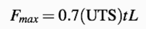
Using the shearing of sheet metal has become the preferred process for major manufacturers. One of the major advantages is the ease and speed with which shearing can be done. Another benefit is the lack of by-products that it produces when compared to drilling or other material removal processes.
What are the common types of shearing?
Regardless of the forming process to be used, the sheet may have to be first cut into the desired shape and size. The types of shearing commonly used in sheet metal fabrication are:
- Shearing is cutting a sheet along a straight line.
- Slitting/ roll slitting cuts a long strip (coil) into narrower widths.
- Blanking is cutting a sheet between a punch and a die to produce a contoured part.
- Punching/ piercing uses a punch and a die to produce a hole.
- Trimming is the removal of excess material in drawn products.
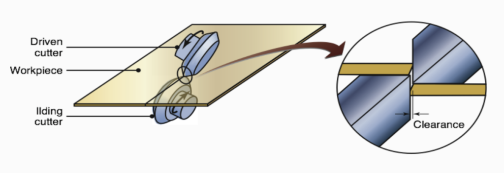
What is rotary shearing?
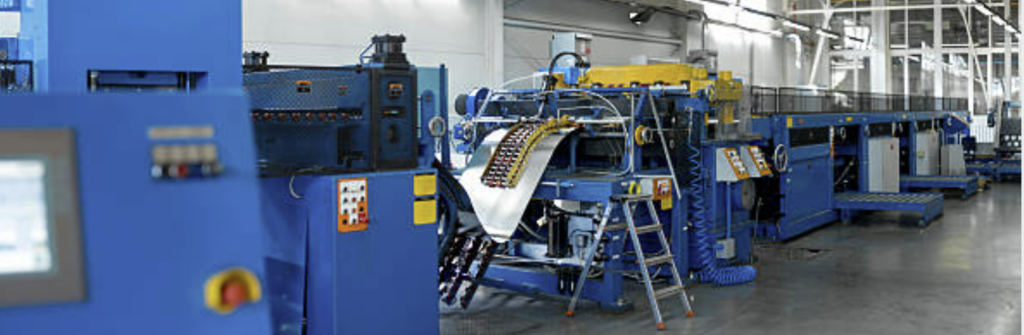
Rotary shearing is a metal removal process used in sheet metal fabrication. This process involves rotating a cutting tool to cut through sheet metal continuously. This process is similar to opening cans or using a can opener. Rotary shearing is typically used for cutting long strips of sheet metal into smaller pieces, such as coils or rolls, with precise dimensions and clean edges.
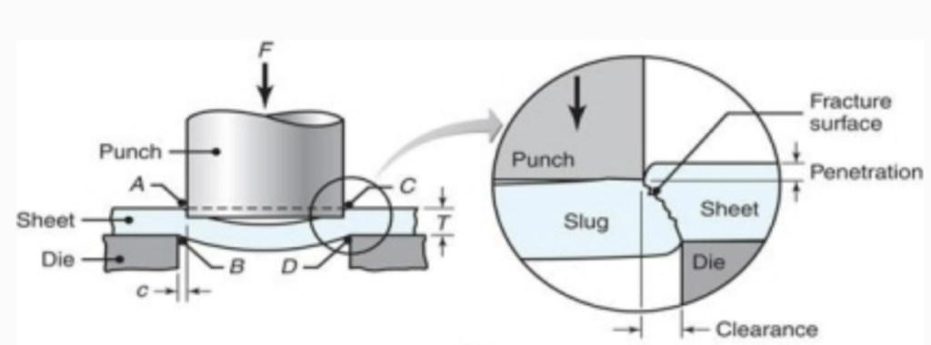
What is a shear zone in metal cutting?
The shear zone in metal cutting refers to the region where the actual cutting of the metal occurs during the shearing process. Understanding the shear zone is important in optimizing the shearing process for achieving clean and precise cuts in sheet metal fabrication. The clearance between the punch and the die affects the quality of the cut and shear zone; as the clearance increases, the material tends to be pulled into the die rather than be sheared. In practice, the clearances usually range between 2 – 10% of sheet thickness.
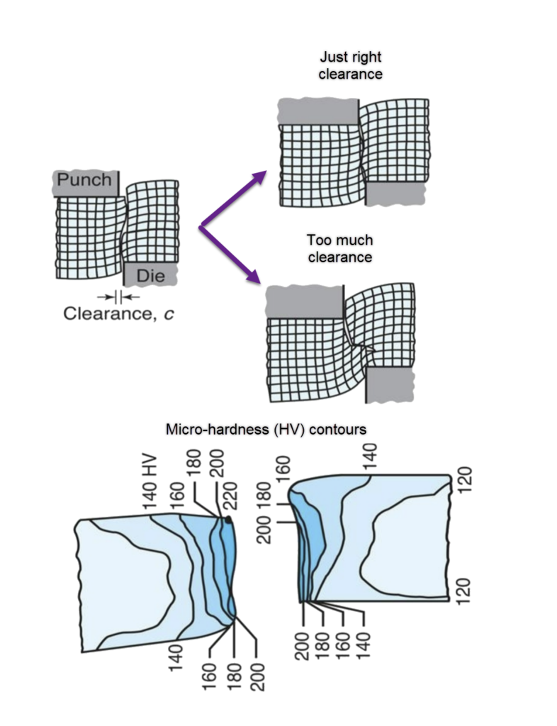
The shear zone typically extends along the line of the cut. The metal in this zone can have different characteristics depending on factors such as the material being cut, the shearing force applied, and the tool geometry. See the pictures above, which show the microhardness (HV) contours for a 6.4-mm (0.25-in.) thick AISI 1020 hot-rolled steel in the sheared region.
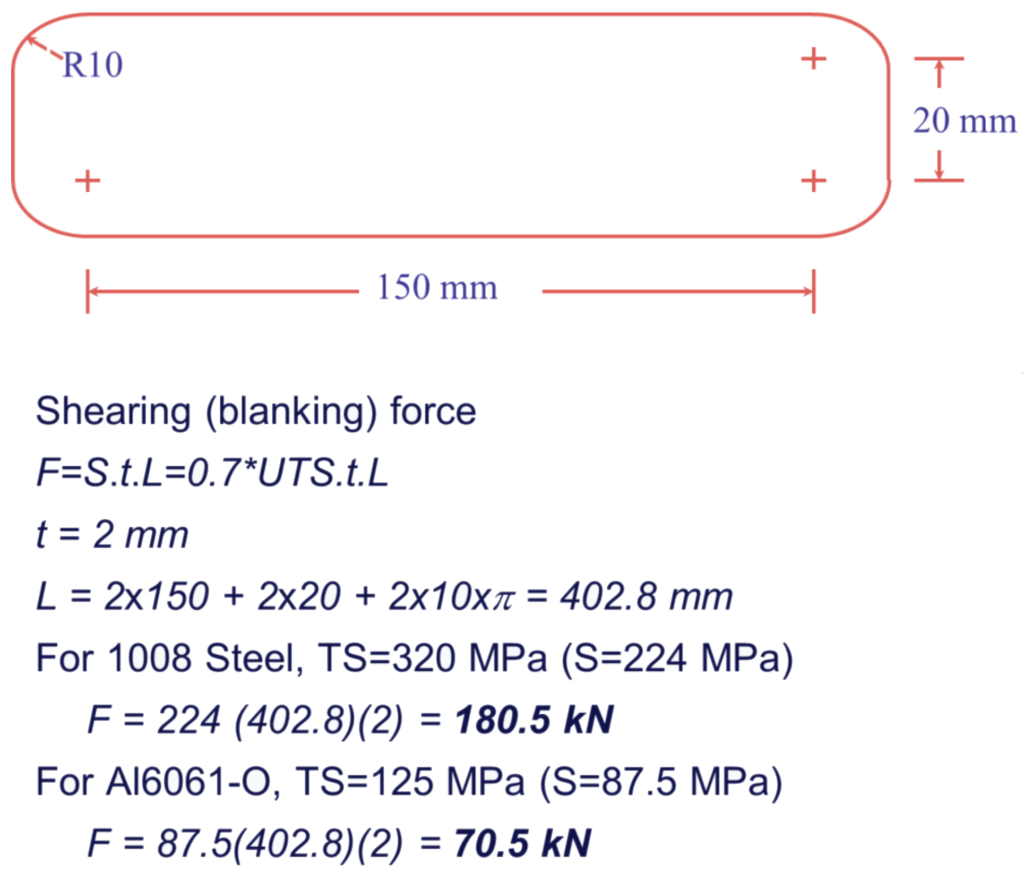
Sample Problem:
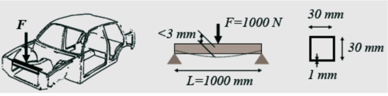
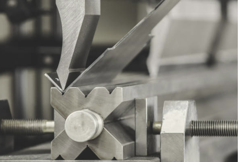
It is proposed to replace the material of a part currently made of 1008 steel with Al6061-O in order to improve corrosion characteristics and reduce weight. The part is made by blanking material strips (See Figure) from a 2-mm thick sheet, then bending them over a radius of 3-mm radius to a final angle of 90o. Calculate the required blanking force for each material.
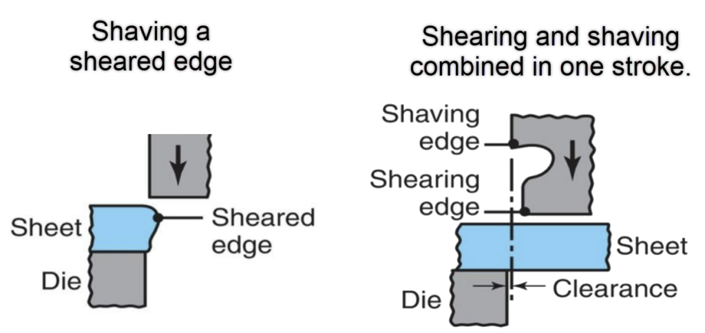
What is the shaving process in metal?
The shaving process in metalworking is a type of precision die-cutting operation. This process involves removing a minimum layer of metal from the edges of a workpiece/blank using a punch-and-die system. By removing the thin layer of material from the edge, you are able to achieve a tighter tolerance (desired dimension) and a better finish (removed burrs).
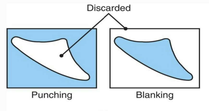
What is blanking vs punching vs piercing?
Blanking, punching, and piercing are different methods used in sheet metal fabrication for cutting holes or creating cut-outs in sheet metal.
- Blanking: Blanking is the process of cutting out a flat piece or blank from a larger piece of sheet metal, typically using a die and a punch. The die is a specially shaped cutting tool, and the punch is a tool that applies the cutting force to create the cut-out in the sheet metal. Blanking is commonly used to create parts with simple shapes, such as circles or squares.
- Punching/ piercing: Punching and piercing are extremely similar; both involve creating holes or cut-outs in the sheet metal using a punch to forcefully penetrate the material. The punch applies a cutting force to the sheet metal, creating the hole or cut-out. The slug can be later removed as scrap, or it can be collected and used as a separate part, depending on the design requirements.
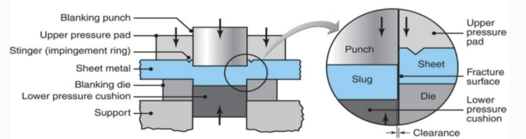
What is fine blanking?
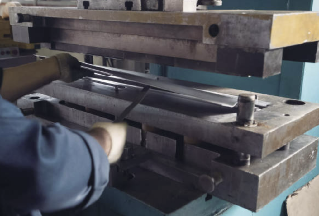
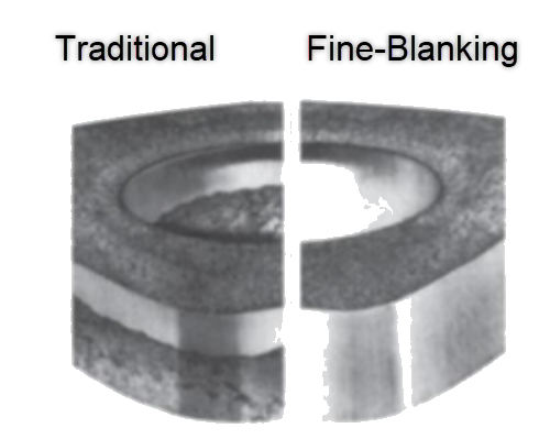
Fine blanking (FB) is a specialized stamping technique that results in a tight-tolerance blank. It is a variation of the blanking process; however, fine blanking takes the blanking process to a higher level of precision and quality. The image below shows the setup for fine blanking. During fine blanking, you have a much tighter clearance between the die and punch when compared to a traditional steering operation.
Fine blanking is capable of producing parts with extremely tight tolerances, often with a burr-free edge finish, and without the need for additional secondary operations such as deburring. This makes it well-suited for producing parts with complex shapes, intricate details, or demanding geometries, where high precision and quality are required. Fine blanking is commonly used in industries such as automotive, aerospace, electronics, and appliance manufacturing, where parts with tight tolerances and high-quality finishes are critical. The image below shows a comparison of sheared edges produced by conventional and fine-blanking techniques.
What is the bend radius for sheet metal?
The bend radius in sheet metal refers to the minimum radius that can be achieved when bending a piece of sheet metal without causing any cracks or defects in the material. The bend radius is measured to the inner surface of the bent part, where the metal is compressed, and it determines the amount of deformation that the sheet metal can undergo without failure.
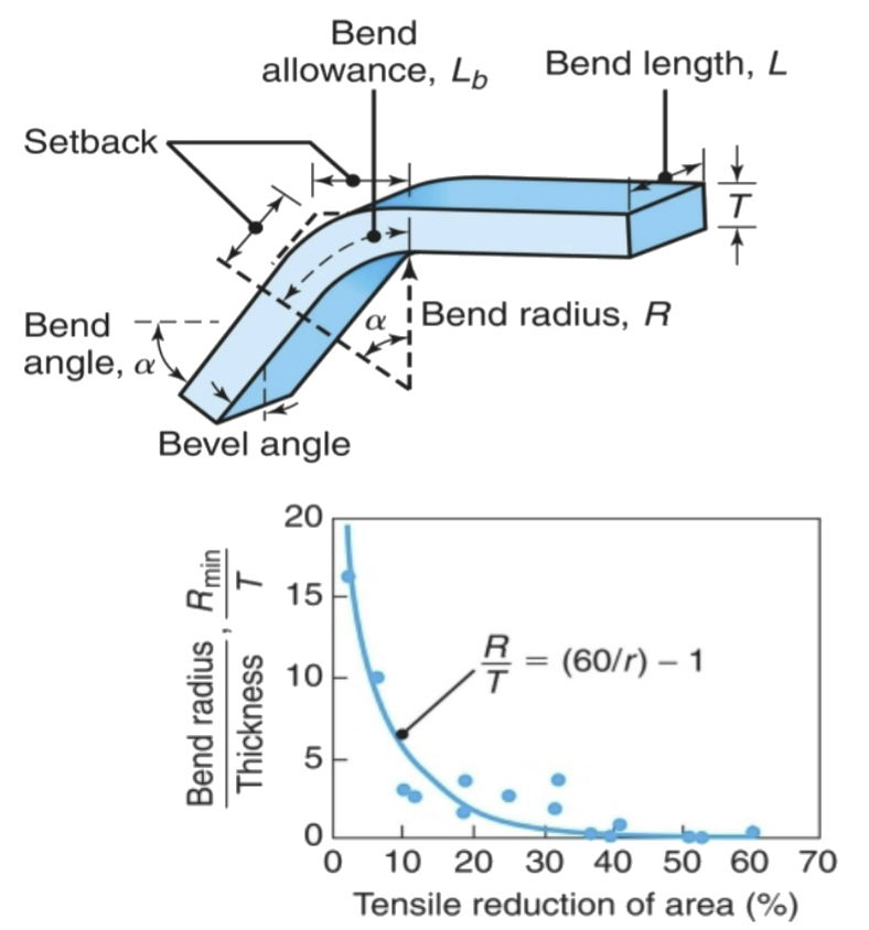
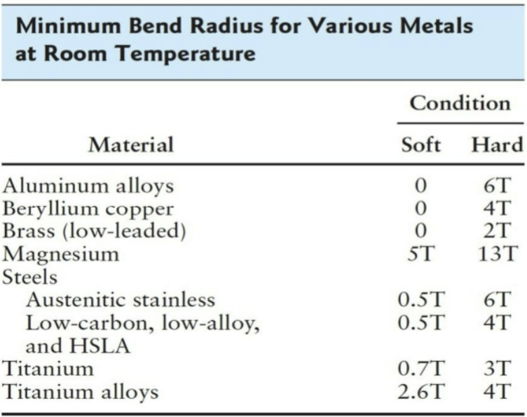
The bend radius is dependent on several factors, including the material type, thickness/ gauge, and material properties, as well as the bending method and tooling used. In general, the bend radius is expressed as a multiple of the sheet metal thickness. For example, a common rule of thumb is that the bend radius should be at least equal to or greater than the sheet metal thickness for most materials. See the chart below, which shows the recommended minimum bend radius for various metals at room temperature.
Bending Mechanics
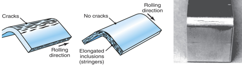
The two pictures on the left show the effect of elongated inclusions (stringers) on cracking as a function of the direction of bending with respect to the original rolling direction of the sheet. The picture on the right shows the formation of cracks on the outer surface of an aluminum strip bent to an angle of 90°. It’s important to remember the narrowing of the top surface in the bend area due to the Poisson effect.
What is the bending operation in sheet metal?
The metal-bending operation in sheet metal fabrication is a process of deforming a piece of sheet metal to create an anticipated shape at an angle and form by applying force to the material along a bend line. The force required to bend sheet metal can be calculated using the following equations:
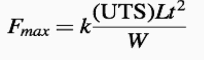
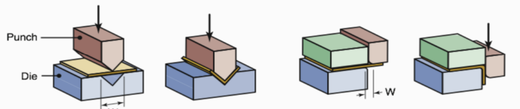
The resulting bend is usually in a ‘V’ or a ‘U’ shape. Bending is one of the most common and widely used methods for forming sheet metal into various shapes and configurations, and it is often performed using specialized tools and equipment. The image below shows common die-bending operations, showing the die-opening dimension W, used in calculating bending forces
What is flanging in metal forming?
Flanging is a sheet-metal forming process that helps strengthen a sheet metal part by bending/folding the edge of a sheet metal or plate to create a curl flange. The flange is created by bending the edge of the sheet metal, resulting in a raised portion that runs parallel to the original surface. As a result, the flanging process reinforces an edge by reducing the flat area and increasing the buckling load. Flanging is commonly used in various industries, including automotive, aerospace, HVAC, and construction, to create functional features and improve the structural integrity of a component.
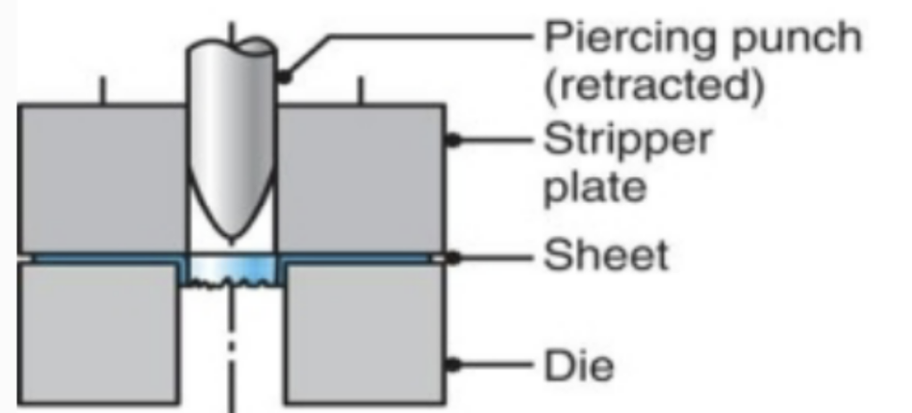
The flanging process can be performed using different methods, such as manual flanging with hand tools, mechanical flanging with power tools or machines, or hydraulic or pneumatic flanging using specialized equipment. The selection of the flanging method depends on factors such as the thickness and material type of the sheet metal, the required flange shape and dimensions, and the production volume. As can be seen in the picture below, a hole does not have to be pre-punched before the punch descends, thus creating the flange. However, the resulting flange will have rough edges along its circumference of the flange. Depending on how the flange is created, thinning of the edges of the flange can also be experienced.
What is the stretch-forming process?
Stretch forming is a metal forming process that involves stretching and bending a sheet of metal or a plate over a die to create a contoured shape. It is commonly used in the aerospace industry to create aluminum skins for aircraft. Stretch-forming is ideal for producing curved or contoured parts with smooth surfaces and precise dimensions.
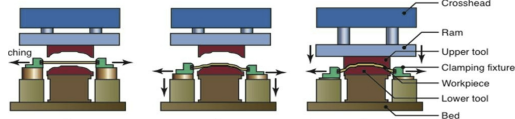
The stretch-forming process typically involves clamping the edges of a sheet metal or plate and applying tension forces to stretch it over a die or form block. The sheet metal is carefully shaped and stretched to conform to the contours of the die, resulting in a formed part with the desired shape. Stretch forming is typically performed at room temperature, although in some cases, heat may be applied to aid in the forming process.
What is a draw bead in sheet metal forming?
A draw bead in sheet metal forming is a localized constriction or indentation made in a die or tool that helps control the flow of sheet metal into the die cavity during the stretch-draw forming of large panels. It is typically used in stamping or drawing operations to help shape the sheet metal into a desired form while also minimizing the blank size needed to make a part.
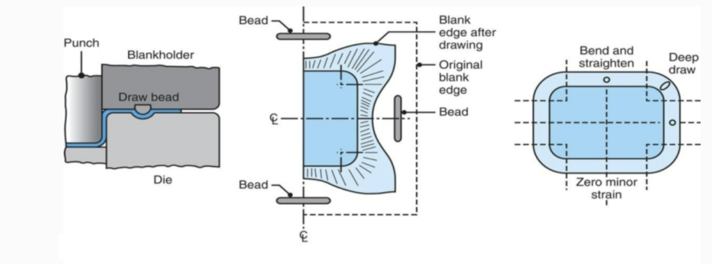
The draw bead acts as a restraining feature, providing a defined path for the metal to follow and preventing wrinkles or tears from forming. It helps ensure uniform material flow and proper forming of the sheet metal, resulting in consistent and accurate parts. The draw beads are always cut away during the trimming operation since they are only forming/stamping aids.
What is the limiting drawing ratio?
The limiting drawing ratio (LDR) is a parameter used in sheet metal forming to determine the maximum achievable depth of a drawn part without defects, such as wrinkles or tearing. It is the ratio of the initial blank to the minimum diameter of the drawn cup (punch diameter).
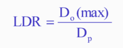
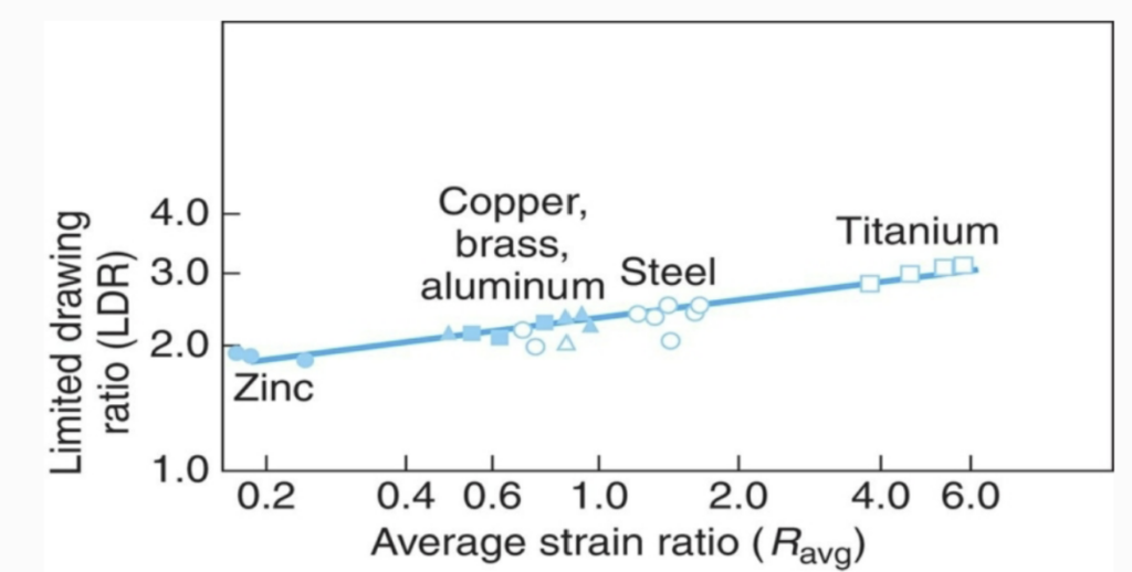
A higher LDR indicates higher formability of the material, allowing for deeper drawing without defects. The LDR is an important consideration in the design and manufacturing of drawn parts, as it helps determine the feasibility and success of the forming process, and influences the tooling and process parameters used in sheet metal forming operations such as deep drawing. When LDR is reached, the drawing force exceeds the force that the wall can support, thus failing. The graph below shows the relationship between average normal anisotropy and the
Limiting drawing ratio for various sheet metals.
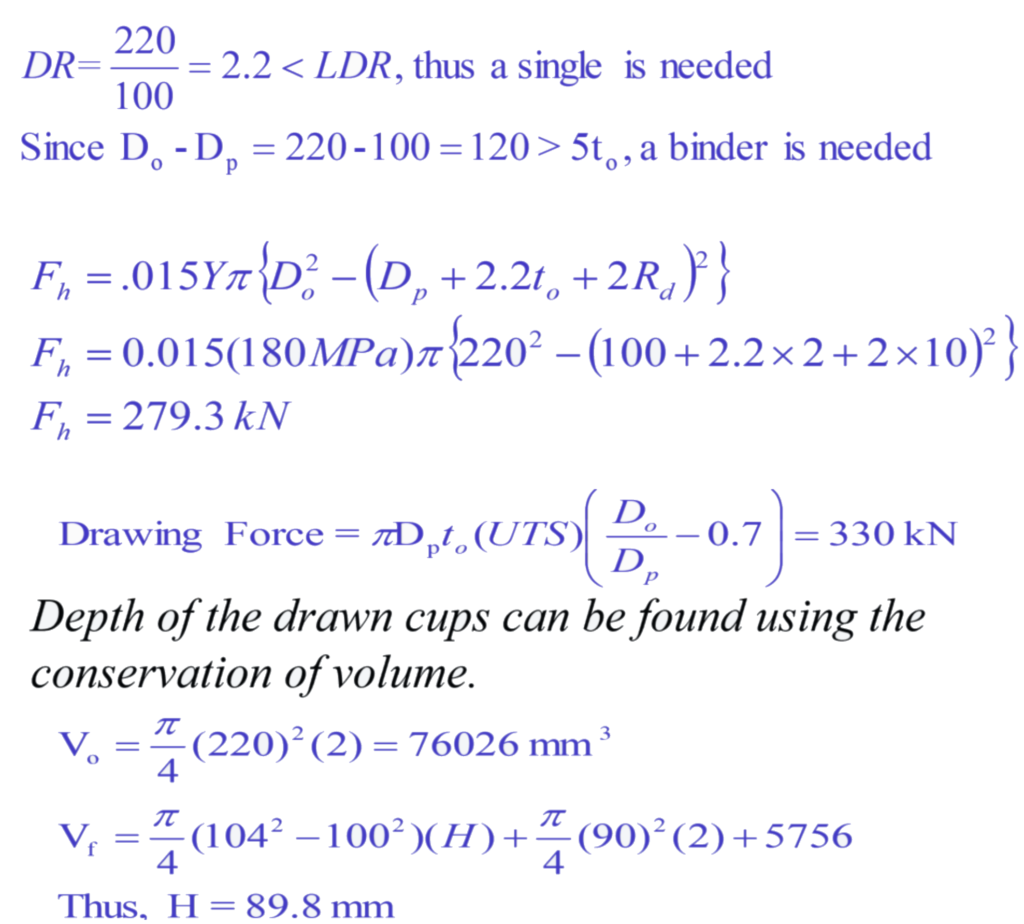
Sample Problem
AKDQ steel with R =1.7 and LDR=2.4, is to be drawn from a sheet into cups using a 100-mm diameter punch and a punch nose radius of 5 mm. The original sheet is 220 mm in diameter and 2 mm thick and the die has 10 mm corner radius. Neglecting frictional effects, and given YS=180 MPa, TS=350 MPa, determine
- the required forces, and
- The depth of the drawn cups if the volume of the radius section is 5756 mm3.
Solution
Best Practices in Sheet Metal Forming
Now that you have a grasp of the fundamentals and techniques, let’s talk about some best practices to keep in mind when working with sheet metal forming. These tips can help you achieve accurate and consistent results in your projects.
Metal Selection:
Choosing the right type and thickness of sheet metal is crucial for successful forming. Consider factors such as the intended use of the product, the required strength, and the forming process you’ll be using. Different materials have different properties and behaviors during forming, so understanding their characteristics is essential.
Design Considerations:
When designing your sheet metal parts, consider the limitations and capabilities of the forming process you’ll be using. Consider factors such as minimum bend radius, tolerances, and tool clearances. Designing with these considerations in mind can help prevent issues such as cracking, warping, and distortion during forming.
Tolerances:
Pay attention to tolerances when designing your parts, as they can impact the accuracy and fit of the final product. Understand the tolerances allowed by the forming process and incorporate them into your design to ensure a proper fit and functionality of the finished part.
Tools and Equipment:
Properly using the tools and equipment for sheet metal forming is essential for achieving accurate results. Familiarize yourself with the operation and maintenance of tools such as press brakes, punches, and dies. Follow safety guidelines and use appropriate personal protective equipment (PPE) to ensure your safety during the forming process.
Technique Execution:
Pay attention to the technique you’re using and follow the proper procedures for each process. For example, when bending, ensure that the sheet metal is properly aligned with the bend line and the tooling is set up correctly. When drawing, make sure that the punch and die are properly lubricated to prevent galling and wrinkling of the sheet metal. Following proper technique execution can result in high-quality formed parts.
Troubleshooting Common Issues
Even with the best practices in place, issues can sometimes arise during sheet metal forming. Let’s look at some common issues and their solutions:
- Springback: Springback occurs when the sheet metal returns to its original shape after bending, resulting in a less accurate bend angle. To minimize springback, you can use a smaller bend angle or overbend the sheet metal slightly to compensate for the springback effect.
- Wrinkling: Wrinkling happens when the sheet metal forms unwanted creases or wrinkles during forming. To prevent wrinkling, you can use a smaller punch diameter, add a blank holder, or adjust the drawing speed to ensure uniform material flow.
- Tearing: Tearing occurs when the sheet metal tears or fractures during forming, usually due to excessive stretching. To prevent tearing, you can adjust the draw ratio, use proper lubrication, or choose a different material with higher ductility.
- Cracking: Cracking occurs when the sheet metal develops cracks, either during bending or drawing. To prevent cracking, you can use a larger bend radius, reduce the forming speed, or choose a material with higher ductility. Proper lubrication and tooling maintenance are also important to prevent cracking.
- Distortion: Distortion refers to the warping or twisting of the sheet metal during forming, resulting in a misshapen part. To minimize distortion, you can use symmetric tooling, distribute the forming load evenly, and use a lower forming speed. Properly clamping and supporting the sheet metal during forming can also help prevent distortion.
Conclusion
Sheet metal forming is a versatile and widely used manufacturing process that allows for the creation of complex and functional parts. By understanding the fundamentals, techniques, and best practices, you can master the art of sheet metal forming and achieve accurate and consistent results in your projects.
Remember to choose the right material, design with the process limitations in mind, follow proper techniques and procedures, and troubleshoot common issues as they arise. With practice and experience, you can become proficient in sheet metal forming and create high-quality products.
So, whether you’re interested in DIY metalworking projects, pursuing a career in manufacturing, or simply curious about how things are made, sheet metal forming is a fascinating field that offers endless possibilities for creativity and innovation. So go ahead, grab some sheet metal, and start exploring the world of sheet metal forming.
References:
- Kalpakjian, S., & Schmid, S. R. (2014). Manufacturing Engineering and Technology. Pearson Education.
- Hearn, E. J. (2006). Sheet Metal Forming Basics. Industrial Press Inc.
- Handbook of Manufacturing Engineering and Technology. (2019). Springer.
- Groover, M. P. (2019). Fundamentals of Modern Manufacturing: Materials, Processes, and Systems. John Wiley & Sons.