Automotive FEA Analysis
Why is FEA important for engineering?
Finite Element Analysis (FEA) involves simulating various physical phenomena using the numerical technique known as the Finite Element Method (FEM). Engineers employ FEA software to streamline the design phase, minimizing the need for physical prototypes and experiments, and enhancing product development efficiency while reducing costs.
A comprehensive understanding and quantification of physical phenomena, such as structural or fluid behavior, thermal transport, wave propagation, and the growth of biological cells, require mathematical analysis. Many of these processes are delineated using Partial Differential Equations (PDEs). However, solving these PDEs computationally demands numerical techniques, with Finite Element Analysis emerging as a prominent method over recent decades.
What is the meaning of FEA?
Finite element analysis (FEA) provides a way for engineers to test various different load cases or failure modes virtually. This helps different OEMs iterate faster and lead to more efficient designs at a reduced cost. In today’s world FAE is vital to helping engineers get a better understanding of how a system works. However any computer software is only as good as the operator using it, and engineers must still ensure that all the assumptions they working with are accurate and true.
What is FEA in the automotive industry?
FEA is a broad term used to cover the use of computational tools to help understand various different load cases in a vehicle. The goal of these virtual models is to discover vulnerabilities in the vehicle design prior to automakers kicking off prototypes or production tools. For example, engineers can use FEA software to run side-impact crash testing (FMVSS 214) on a vehicle prior to ever having built any prototype vehicles. If they see that a vehicle is not meeting the desired targets they are able to quickly modify the vehicle geometry or change the material type/ gauge of the weakest link in the design. An example of how FEA is used in the automotive industry can be seen below:
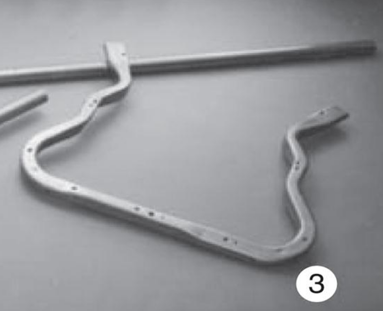
FEA analysis on a front motor compartment cross member
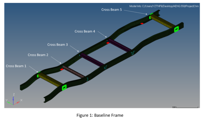
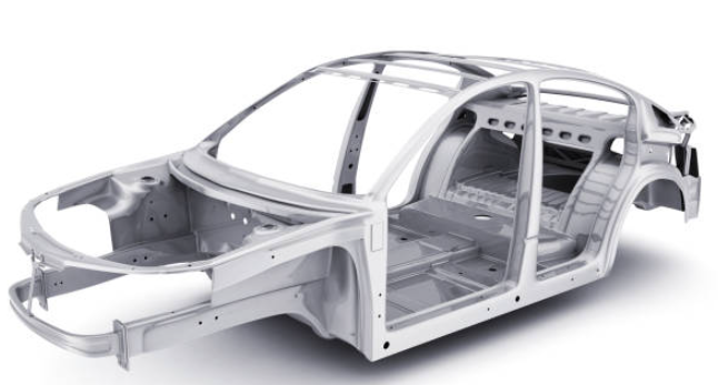
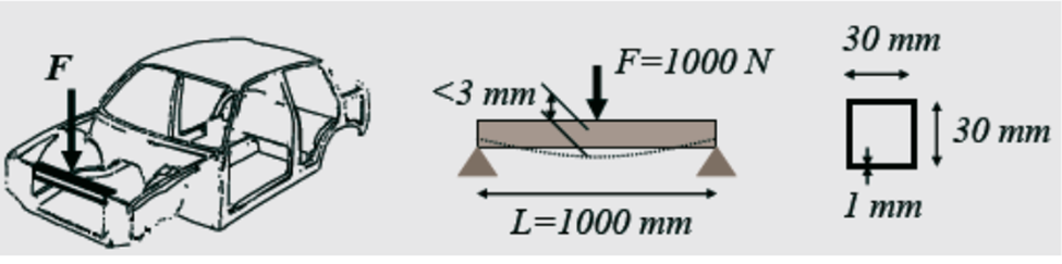
This project explores the deflection of a body-in-white (BIW) front motor compartment cross member, which is subject to aerodynamic loading. One function of a front motor compartment cross member is to maintain the hood latch interface to prevent the hood from opening under normal vehicle operating conditions. To simplify the modeling of this problem the front motor compartment cross rail will be shown as a square 30 mm x30mm beam which is fixed at both ends (beam bending problem). The aerodynamic load will be modeled as a 1000N point load applied at the center of the beam. The Beam is made from steel with a modulus of elasticity of 210GPa, a young’s modules of 0.3, a density of 1000 kg/m3, and a yield strength of 210 MPa. See Figure 1 below: problem description.
Model Development- Loading and Boundary conditions:
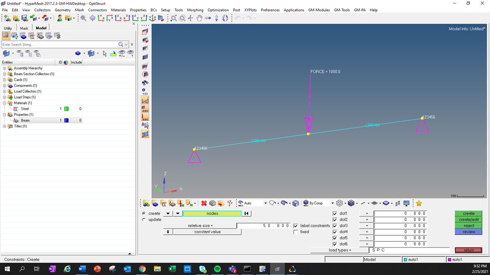
The problem was solved using Altair HyperMesh. The front motor compartment cross member was modeled as both a 1D and 2D element. To study the impact of the mesh size, the 2D front motor compartment cross-member mesh was varied from 1mm – 5mm. The 1D element was created by first placing 3 nodes and connecting them with a beam (1D section from the main menu). The properties of steel were created and assigned to the beam using the CBEAM command. In addition to the properties, the beam element cross section was also assigned using the same command. Finally, using the boundary condition tab, two ends of the beam were fixed and a 1000N load was applied to the center. The result can be seen at the top of the next page in figure 2: 1D model setup.
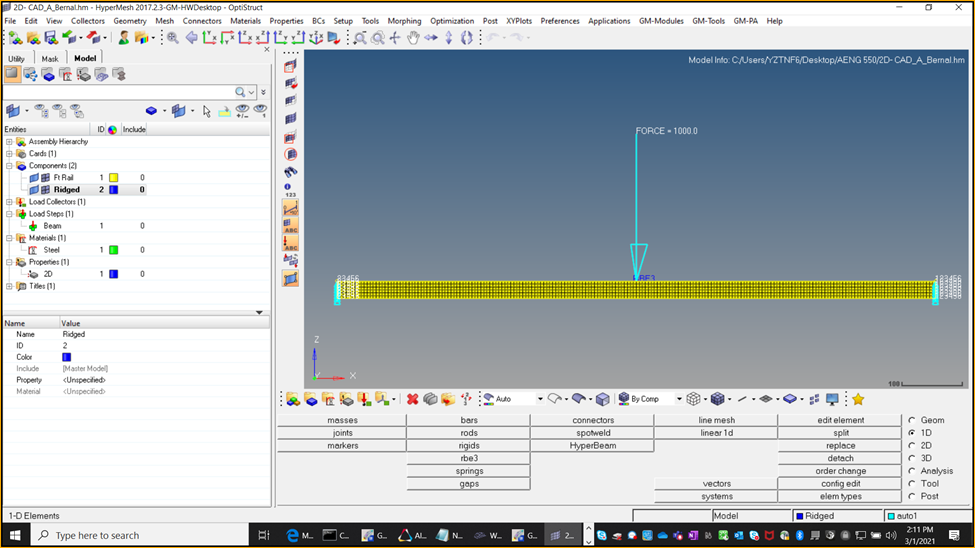
To model the beam as a 2D element the first step was to create the 4 nodes which will make up the square end cross-section of the beam. These nodes are then connected using the geometry tab to create a square. Then the square is then extruded, and a beam is formed. It’s important to assign the correct properties (beam thickness) and material to this beam to ensure the correct result see figure 4.

Unlike a 1D element, a 2D element requires you to mesh the beam. Whenever you are meshing any part, it is important to make sure the elements are as close to square as possible, since this part has no round edges which is not much of an issue. When applying the boundary conditions, it is important to select all the nodes at each of the ends of the beam. The smaller the mesh size, the more nodes you will have to select. Make sure each of these nodes at the ends is constrained by all 6 degrees of freedom to represent it being clamped down. Since you are applying a point load to the beam, you first need to create a reinforcement (rbe3 under 1D menu) to ensure your load is being distributed among an area in the center. Failure to do so will skew your results since the top of the beam subject to the load will deform much more than the opposite end. See the figure 5 model set up below.
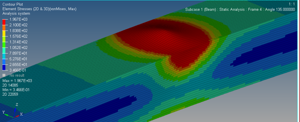
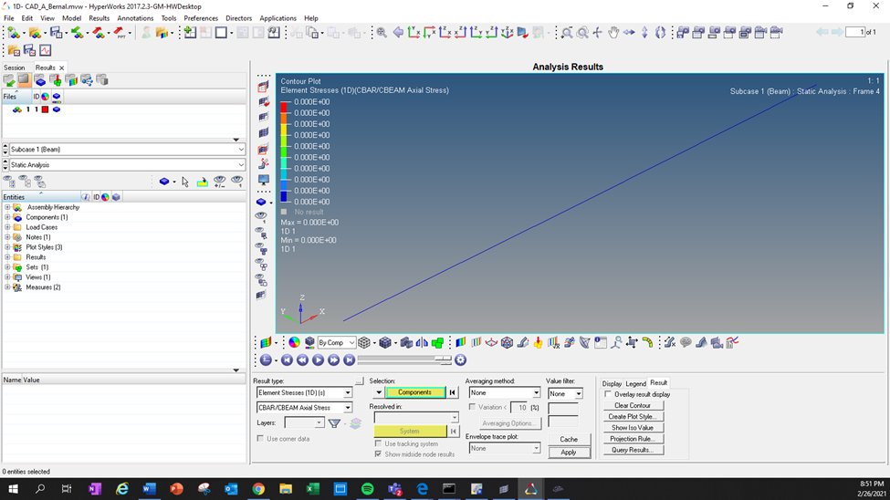
Just as before, once the model has been created, the boundary conditions applied, and the rbe3 reinforcement in the center of the model you can run your model using Optistruct. Once the HyperWorks solver has finished running your model, you can then view your results and perform post-processing using HyperView. See Figures 6A and 6B to view the results from the 2D model on the next page.


Discuss your results:
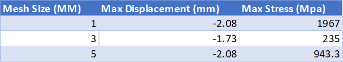
When comparing the effects of varying the size of the mesh the results were very interesting and not what I expected. Even though the displacement did not vary much (-1.73 mm– -2.08mm) the results stress varied drastically from 235 MPa – 1967 MPa. Of all the three trials conducted the most realistic appears to be trial 2 with the mesh size of 3mm. See table 1: 2D displacement/stress result below.
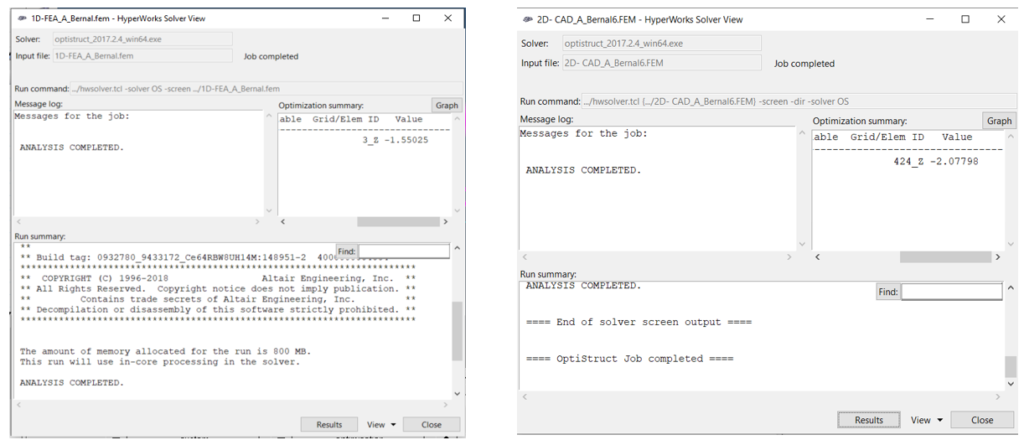
When comparing the effects of running the model 1D v 2D the results were less surprising. The displacement on my 1D model was less than on my 2D model. Since the 1D model had the least number of nodes it is expected that the result would be the least accurate. Unfortunately, I was not able to get results for stress for my 1D model. The only logical reasoning behind this was since it was modeled as a line it has no theoretical area making it impossible to calculate stress. Further trials would need to continue to investigate. See table 2: 1D v 2D displacement/stress result below.

Sample HyperWorks solvers can be seen below with calculated displacement for 1D and 2D model.
Conclusions and recommendations:
In conclusion, to receive better results I would recommend modeling the load as a distributed load along the majority if not all of the beam. This will help spread out the load among a greater area and will increase the accuracy of the results. The reason I believe my stress was so high for the 2D (1mm mesh & 5mm mesh) was that HyperWorks seems to treat my load more as a point load and would not distribute amongst the full beam as I had hoped. See the picture below. If I were to continue with a point load again I would recommend increasing the area of the rbe3 in hopes of improving the results of the 1mm and 5mm mesh models.