Understanding Combined Axial Loading and Bending: How They Impact Structural Design
What is a combined loading?
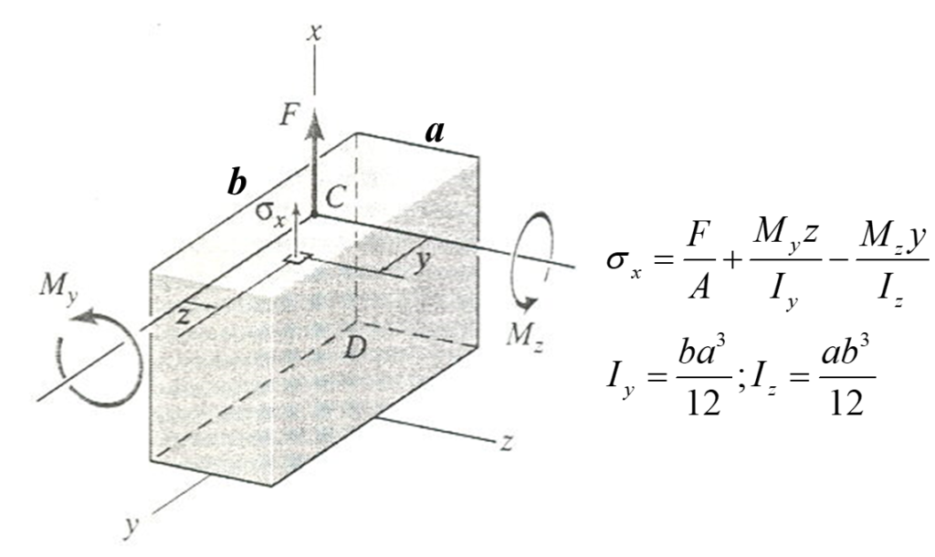
The objective of combined loading is to evaluate the stresses of a structural member when exposed to a variety of loads. Basically, these are forces that act on a structure in different ways, and understanding how they interact is crucial for creating buildings, bridges, automotive chassis and internal combustion engines. To get a better understanding of combined loading, it is common to make a cross-section through the area of interest to evaluate the inner loading/moments at the center of the section for equilibrium.

What are the different types of loading in the combined loading test?
During combined loading, the part can experience various types of loads simultaneously.
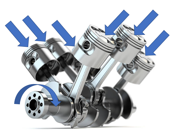
Torsional stresses are loads experienced by a part due to twisting. This can be seen in an engine crankshaft as it turns inside an engine. The higher the RPMs, the greater the torsional load on the crash shaft.
Another type of load which a part can be subject to is bending moments. There are two types of bending: positive bending, which causes the top of a structure to compress and the bottom to stretch, and negative bending, which has the opposite effect. Bridges experience bending forces that can be caused by things like wind, earthquakes, and even the weight of the structure itself.
Axial loading is simply a force that’s applied in a straight line along the length of a structural element. There are two types of axial loading: tensile forces, which pull on the structure, and compressive forces, which push on it.
Finally, the last type of load is a shear load, an example of a shearing stress is the load required to chip away at a material during any machining operation.
What is the importance of combines stresses?
So why is combined loading important? When a part is subject to multiple loads, all acting simultaneously, the multiple forces interact in ways that can be difficult to predict. For example, if you had a part subject to both and axial and bend stress, such as in a vehicle chassis while off roading, the bending forces can cause the structural element to twist or buckle, which can affect the axial forces. Likewise, the axial forces can affect the bending forces. When designing a structure, engineers have to calculate the combined forces and stresses, in order to make sure that it can withstand all the forces that it’s likely to experience.

There are a few ways to solve combined loading problems. For example, the superposition method is used to determine the combined effect of two or more stresses acting over the cross-section of the member. The superposition method states that first you need to break the problem into parts where only one type of load acts. Then you solve for the stresses resulting from the load. At last, you re-arrange the solutions to solve the entire issue.
Why is yield criteria important?
A yield criterion is a theory that establishes the limit of elasticity in any engineering material and the start of plastic strain under regardless of the combination of stresses.
What is an example of failure theory?
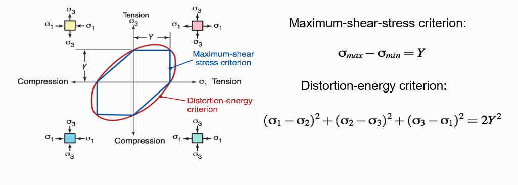
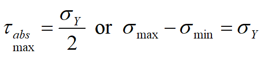
So, imagine you have a material that you want to use for a certain application. You need to make sure that the material won’t fail under the stresses it’s going to experience. One way to do this is to use failure theory, which basically helps you predict when a material is going to fail under the action of external loads. For ductile materials the maximum shear stress theory states that failure occurs when the shear stress on any plane reaches the value, 1/2 yield stress.
What is maximum distortion energy?
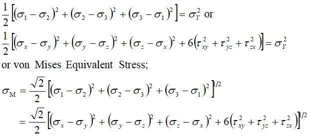
One of the most common types of failure theory is the maximum distortion energy theory, which is also called the von Mises criterion. Basically, it says that yielding is assumed to occur when the energy associated with the change of shape of a body undergoing multiaxial loading is equal to the energy of distortion in a tensile specimen when yielding occurs at the uniaxial yielding stress. The distortion energy takes into account both the normal stresses and the shear stresses that a material is experiencing.
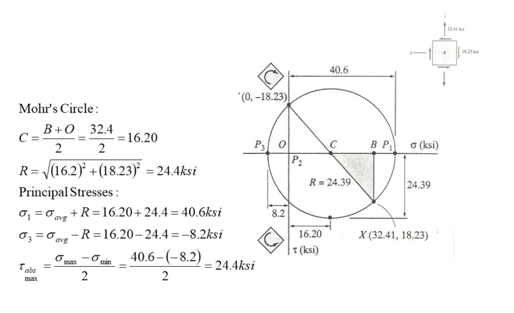
What is Mohr’s circle used for?
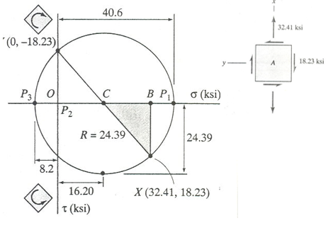
Now, how do we visualize all these different stresses and predict when a material is going to fail? That’s where Mohr’s circle comes in. Mohr’s circle is a graphical representation of the transformation equations for plane stress. It is helpful in visualizing the relationships between normal and shear stresses acting on an element at any desired orientation so you can predict when and where a material is going to fail. It looks like a circle with points on the edge that represent the different stress values. By drawing Mohr’s circle and calculating the different stresses, we can figure out if a material is going to fail and where that failure is likely to occur.
Why does combined loading matter?
So why does combined loading matter? Well, if you don’t factor in the combined axial loading and bending forces, you could end up with a structure that’s not strong enough to withstand the stresses that it’s likely to experience. This could lead to collapse, which would obviously be catastrophic. t’s all about predicting when a material is going to fail and making sure we use materials that can withstand the stresses they’re going to experience. By understanding how these forces interact, engineers can push the boundaries and creating amazing things, but they can do it in a safe and responsible manner.
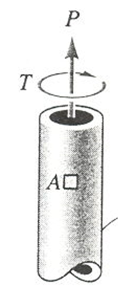
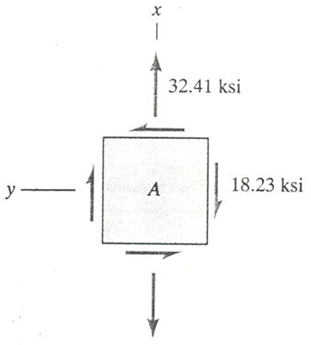
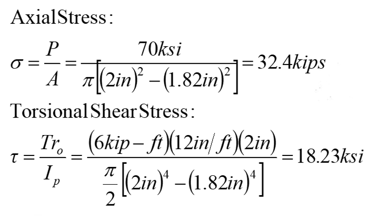
combined loading sample problem:
The section of the pipe at A is under combined loading due to a tensile force P=70 kips and a torque T=6 kip-ft. The pipe has an outside diameter of 4.0 in. and an inside diameter of 3.640 in. Determine the maximum shear stress at point A on the outer surface of the pipe. The radial stress at this point is zero. The yield strength in tension of this pipe is 95 ksi.