Body-on-Frame: Truck Design
Have you ever asked yourself what are the natural frequencies a truck body-on-frame is subject to? Well, you would if you were trying to design one! One of the key areas of focus in automotive manufacturing research is the reduction of chassis mass and production costs. However, when you begin to reduce the mass of the chassis, the chassis becomes more susceptible to significant vibrations, primarily stemming from the engine and road irregularities.

Truck chassis refers to the automotive body structure commonly used on trucks: ladder frame construction/ Body-on-frame (BOF) plus the driveline. This Truck chassis sometimes referred to as a rolling chassis exhibits natural frequencies that manifest in various modes of vibration. Among these modes, the first, second, and sixth are considered global vibrations, while the rest are categorized as local vibrations. This article will study how to influence the natural frequencies of a traditional body-on-frame/ ladder-style assembly of the truck chassis.
What is the meaning of body-on-frame?
Body-on-frame (BOF) construction goes back to the early years of the automotive industry when wealthy individuals would buy rolling chassis from automakers such as Bugatti or Rolls Royce. They would then turn around and go to a coachbuilder/body-maker who would custom-build the passenger-carrying compartment of their automobile. As a result, no two vehicles were the same, since each vehicle had both DNA from the auto manufacturer and styling from the coachbuilder.
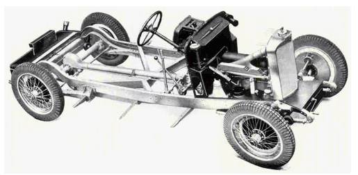
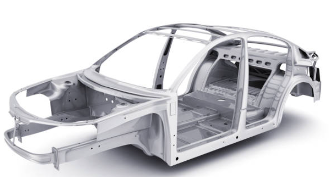
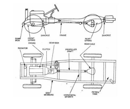
Before the 1940s, virtually all automakers designed vehicles with body-on-frame architectures. Today body-on-frame designs are still used on pickup trucks and large SUVs. A body-on-frame construction is one in which the structural load-carrying metal frame is separate from the body-in-white. All the chassis and powertrain components mount directly to the frame creating what is called a rolling chassis/ ladder chassis.
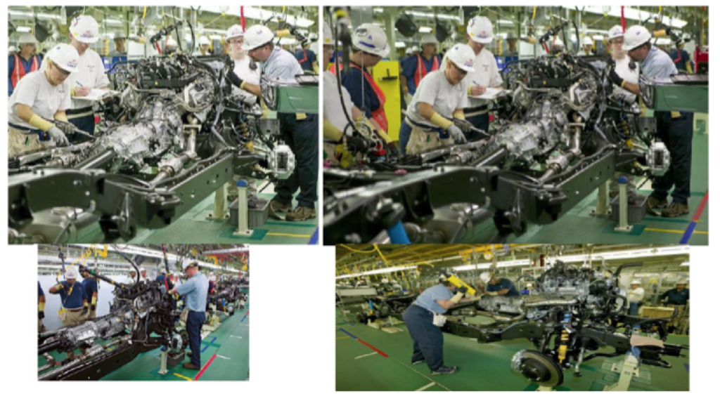
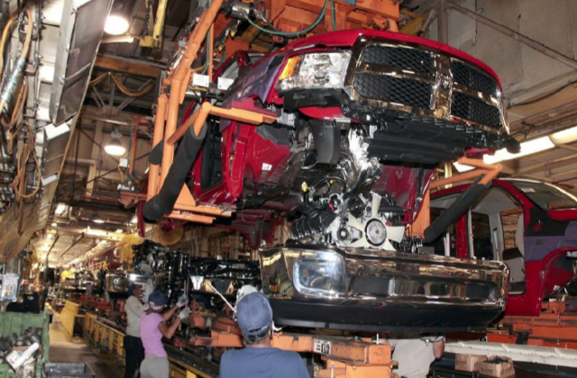
The rest of the vehicle would then get assembled to the upper structures of the Body-in-White to create the “coach” which would be bolted to the rolling chassis during what is known as the body drop or marriage in the assembly process.
Ladder frame truck chassis
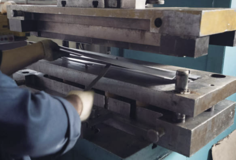
The truck chassis stands as a vital component, imparting strength and stability to the vehicle in diverse conditions. Serving as the backbone of any truck, these frames deliver both strength and flexibility, with steel being the predominant material, although aluminum is gaining popularity for their construction. Given that the chassis forms the foundational support for heavy-duty vehicles, its primary role is to safely carry the maximum load across all operational conditions. Additionally, it must absorb engine and driveline torque, withstand shock loading, and adapt to twisting on uneven road surfaces.
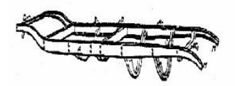
To achieve this performance automakers must meticulously design and rigorous testing the construction of vehicle frames. The ‘ladder’ type frame construction is specifically designed to provide robust support for the body and payload, while simultaneously offering torsional flexibility, particularly in the region between the gearbox cross member and the cross member ahead of the rear suspension.

This chassis flexibility is essential, as a rigid frame is more susceptible to failure compared to a flexible one capable of ‘weaving’ when subjected to challenging conditions. Furthermore, a torsionally flexible frame has the added advantage of reducing suspension loading when the vehicle encounters uneven surfaces.
Is body-on-frame better than unibody?
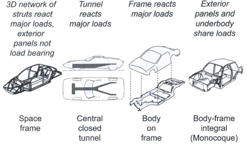
When comparing different types of automotive structure designs such as space frame vs unibody vs body-on-frame (BOF) designs, it’s important to remember each type of architecture has its advantages and disadvantages. Of these three the most popular type of vehicle constructions for the vast majority of passenger cars /trucks are either unibody or BOF.
body-on-frame design- Advantages
One of the advantages of a body-on-frame design is it performs better from an NVH (noise, vibration, and harshness) standpoint. Body-on-frame architecture also enables larger hauling and towing capacity, because this architecture isn’t as susceptible to twisting forces when compared to a unibody vehicle. BOF vehicles also tend to have a higher ground clearance making them more off-road worthy, when compared to a unibody design, which is why they are the preferred execution for the majority of pick trucks and large SUVs.

Currently, there are only 3 trucks on the market that do not use a BOF design, the Honda Ridgeline, Ford Maverick, and the Hyundai Santa Cruz. It is important to note that the Honda Ridgeline competes in the mid-size truck segment and the Ford Maverick and Hyundai Santa Cruz compete in the compact truck segment. None of these trucks compete in the full-size truck segment, which is where the majority of the truck sales occur.
Unibody frame – Advantages
However, a unibody frame also does have its advantages. For starters, a unibody construction is much more efficient from a structural load path perspective. As a result, unibody vehicles are generally lighter, less stiff, and less likely to roll over than a comparable body-on-frame vehicle. For that reason, the vast majority of passenger cars and crossover SUVs are built with a unibody design, rather than truck-like body-on-frame construction.

A recent study conducted by the University of Washington also found that unibody vehicles are superior to body-on-frame about occupant safety and crashworthiness. Occupants of passenger vehicles that crashed with compact unibody SUVs were at an 18% lower risk of death compared to those that crashed with compact body-on-frame SUVs [1].
Vibrational Effects of a Truck Chassis
The chassis plays a crucial role in vehicle systems, particularly for off-road vehicles, serving as an integration point for key truck components such as suspension, engine, body structure, and truck bed. Throughout the evolution of off-road vehicles, the appearance of chassis designs has remained relatively consistent, indicating a slow and stable progression over the years. This has prompted many researchers in the automotive industry to engage in chassis manufacturing technology and development.
In the current trend of truck design, there is a focus on reducing costs and increasing transportation efficiency primarily for the heavy-duty and commercial truck industry, leading automakers to develop lighter trucks. However, lighter chassis designs may also introduce vibrations due to dynamic forces from the engine, transmission, and road irregularities. Consequently, these dynamic excitations can lead to ride discomfort for the occupants, safety issues, ride and handling problems, and potential damage to the cargo.
Natural Frequency of a Body-On-Frame Truck Chassis
Identifying the natural frequency modes is crucial, as all structures, including truck chassis, have natural modes that can contribute to excessive noise, vibration levels, and premature failures if excited. The following modes can vary based on the BOF design of the rolling chassis. The following is an example of the natural frequencies of a truck frame:
The initiation of local vibration begins with the third mode at around 29.6 Hz. The predominant mode is torsional, occurring at 7.219 Hz, with both ends of the chassis experiencing the maximum translation. The second mode, identified as vertical bending at 17.153 Hz, results in the front part of the chassis undergoing the maximum translation.
Modes three and four involve localized bendings at 29.612 Hz and 33.517 Hz, respectively, with the top hat cross member experiencing the highest translation. The fifth mode, a localized torsion mode, also induces significant translation in the top hat cross member, which serves as the mounting location for the truck gearbox.
What you will notice is that each mode is defined by its natural frequency, damping, and mode shape. The operating deflection shape of a structure is typically dominated by a mode at or near its natural frequency. This article focuses on the factors influencing the natural frequencies of the chassis frame, utilizing finite element analysis (FEA) to understand this behavior.
Improving the natural frequency of a Body-on-Frame:
This project aims to identify the normal modes of the vehicle frame and then improve the frequency by 1Hz using HyperMesh and OptiStruct. The frame that will be studied during this project is a traditional body-on-frame ladder-style assembly see Figure 1: Baseline Frame. The truck chassis comprises side members connected by a sequence of cross members, creating a ladder-like structure. These components were designed with a primary focus on functionality, offering minimal torsional stiffness.

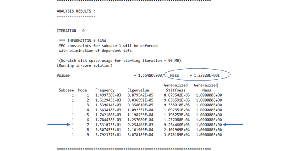
The provided CAD model was run using HyperMesh and OptiStruct to determine the baseline mass and natural frequency. All components in the frame were assumed to have been made from steel with a modulus of elasticity of 210GPa, a Young’s modulus of 0.3, and a density of 7.9 x 10⁻⁶ kg/mm3 The baseline natural frequency for the model was 15.3 Hz and a mass of 122.8 kg See Table 1: Baseline Analysis Result at the top of the following page.
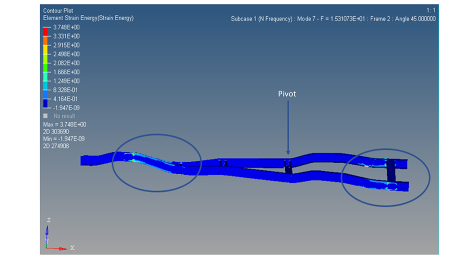
After analyzing the 3D results in HyperView the following observations were made. First of all, the whole frame seems to pivot about the 4th cross bream which can be seen below in figure 2. When the model was set to strain energy contour plot, the highest strain that was observed in the model was where cross beams 1 and 5 were welded to the side beam rails. This makes sense since they were the furthest cross beams from the pivot, so they were subject to the greatest deflection resulting in the most significant stress and load.
Trial 1- Lighting Holes:
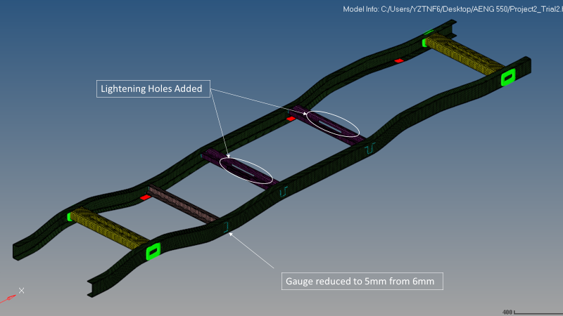
To reduce the natural frequency of the whole assembly, cross beam 2 was up-gauged from 4mm to 6mm, and cross beams 3 and 4 were up-gauged from 5mm to 6mm. The reason these cross beams were selected to up gaged is that they were closest to the pivot points so they would be able to provide the frame with additional rigidity.
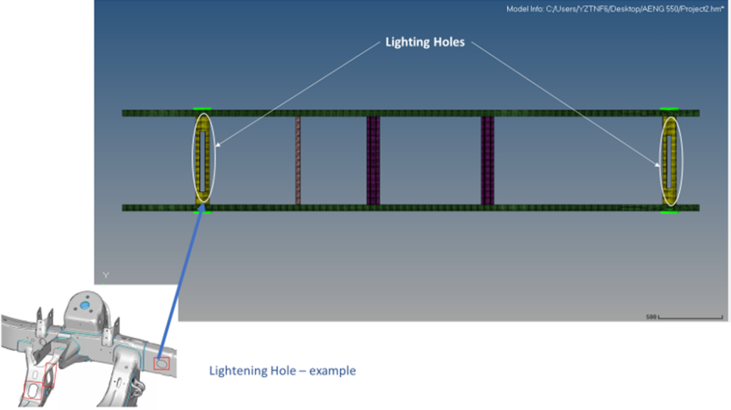
However, since increasing the mass of the assembly would be seen as a negative impact lightning holes were added to cross beams 1 and 5. For ease of modeling, the lightning holes were modeled as just one large hole in the center of the beam. This large hole would not be design intent and several smaller holes would be added that would span the full cross member. See Figure 3: Trial 1 Ladder Frame Geometry.
Results – Trial 1
The result of the modifications was as follows: The natural frequency was reduced to 9.32 Hz a reduction of almost 6Hz from baseline. This was achieved while keeping the mass almost identical at 122.4 kg. See Table 2: Trial 1 Result at the top of the following page.

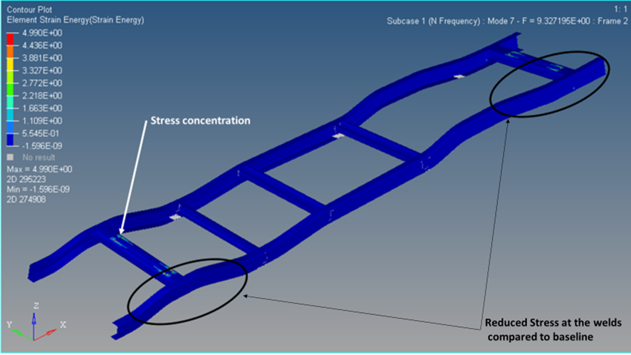
These results were also reflected in the 3D HyperView model, as the strain energy at both cross beams 1 and 5 was significantly less than was previously observed during the baseline model. The model did however still pivot about the same cross beam at cross beam 4. The other notable change that was observed was the stress that formed around the lightning holes in beams 1 and 5. This was to be expected since the holes added to the part act as stress concentrations. Overall, the amount of stress experienced in the part was reduced. Figure 4: Trail 1 Contour Strain Plot
Trial 2 – Lighting Hole and Gauge Reduced:
As a final iteration, cross beam 2 was downgauged from 6mm to 5mm to observe the impact on the natural frequency. Additional lightning holes were added to cross beams 3 and 4 to further reduce the mass of the system. The reason this trial was conducted was to determine the effectiveness of cross beam 2 in dampening vibration while trying to keep the gauges of the cross beams as close to the baseline as possible. See Figure 5: Trail 2 Ladder Frame Geometry Below.
Results – Trial 2
The result of the iteration was as follows: The natural frequency was slightly reduced from 9.32 Hz to 9.30 Hz. As a result, it can be concluded that cross beam 2 is not a major contributor to reducing the natural frequency of the assembly. However, the mass of the system was reduced by 2.2kg down to 120.2kg for the whole assembly. See Table 3: Trial 2 Result below.
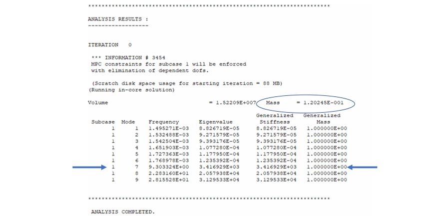
The strain energy contour plot validated the results observed in Table 3. The stresses the beam was subject to were about the same as trial 2 when comparing the mode 7 frequency strain energy contour plot. The pivot of the assembly also remained the same. Figure 6: Trail 2 Contour Strain Plot below.

Conclusion:
When determining how I was going to reduce the natural frequency of the assembly, I contemplated various solutions. Some of them included adding additional cross beams between beams 4 and 5, and adding brackets or reinforcement to the center of the assembly, thus stiffening it up to reduce the movement.
However, all these solutions would add additional parts, mass, and welds, all of which translate to an increased manufacturing cost of the frame. Adding additional parts between cross beams 4 and 5 might also cause integration issues with other components such as the fuel tank which would usually be packaged at the rear of the vehicle.
By increasing the mass, you also negatively affect the vehicle performance/ fuel economy and range of the vehicle. Natural frequency is defined as the square root of the spring coefficient divided by mass. Therefore, the strategy I pursued during this project involved changing the mass to change the frequency.
By adding mass where required but reducing the overall mass of the frame, I could reduce the natural frequency well below the 1Hz requirement. Using HyperView, I could pinpoint which cross beams had the biggest effect on the natural frequency and add lightning holes to the other cross members to reduce the mass of the system.
References:
- Eric M. Ossiander, Thomas D. Koepsell, Barbara McKnight, Crash fatality risk and unibody versus body-on-frame structure in SUVs Accident Analysis & Prevention, Volume 70, 2014, Pages 267-272, ISSN 0001-4575, https://doi.org/10.1016/j.aap.2014.03.019 (https://www.sciencedirect.com/science/article/pii/S0001457514001067)