Unibody Torsional Rigidity
Torsional and bending rigidity is a critical parameter for any automobile, especially vehicles with a unibody construction. However, bending rigidity isn’t as critical as torsional rigidity in the design of a vehicle. Unibody torsional rigidity is a measure of the force required to induce a one-degree “twist” in a car’s body structure. Naturally, a higher value is indicative of superior performance in this aspect.
From the consumer’s viewpoint, what advantage does a car with high torsional rigidity offer? A vehicle with higher torsional rigidity gives the driver and passengers a more solid and stable sensation. This is most noticeable while driving, especially on uneven/ bumpy roads. From an NVH perspective, a vehicle with higher torsional rigidity also experiences less squeak and rattle. Since the body structure exhibits less twisting and flexing when subjected to excess forces and loads transmitted from the road. Due to these advantages, luxury cars and sports cars, in general, tend to possess higher torsional rigidity.

Automotive Body Structure/ Chassis explained
The skeleton or supporting structure of a automobile traditionally was referred to as its chassis, or vehicle frame. It serves as the primary framework to which all other components are bolted/ attached.
Before the 1930s, the majority of cars featured a distinct structural frame/chassis independent of their bodies. This type of construction is commonly known as a body-on-frame (BOF) construction. Recently, the unibody construction has evolved and grown in popularity. Currently, unibody construction has become prevalent in passenger cars and some SUVs. Unibody body structures have even begun to spill over into the truck segment most notably with the Honda Ridgeline.
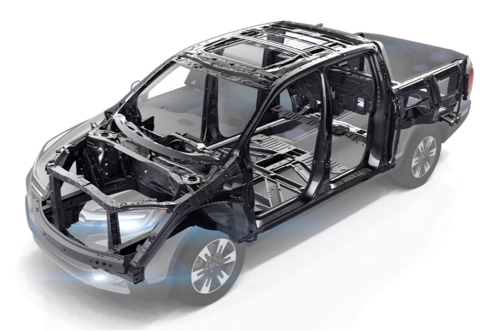
Honda states that the Ridgeline uses a unibody architecture because this design provides 2.5 times greater bending rigidity and 20 times more torsional rigidity compared to the conventional Body-on-frame construction.
When did unibody cars become common?
Automakers like Audi started experimenting with a body frame integral concept (BFI), commonly referred to today as a unibody, in the 1920s. However, it wasn’t until after the 1960s, that the new unibody design strategy, started being used throughout the industry. The switch from body-on-frame (BOF) construction to more unibody architectures was a key enabler for the future widespread use of high-strength steel (HSSs).
Unibodies exhibit increased structural rigidity as forces are distributed across the entire vehicle, allowing for the use of less material and reducing vehicle mass. Consequently, this leads to enhanced fuel economy, improved handling, faster acceleration, and deceleration. Since the body and frame are designed as one system, there is no duplication of parts. This also helps unibody vehicles’ with crash energy management improving overall crashworthiness.
What does unibody mean on a car?
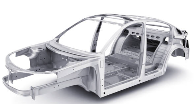
Unibody construction is where the chassis and frame are merged. This type of vehicle frame architecture is the most common in today’s car market. This type of construction is most prevalent in sedans and compact to midsize SUVs/ crossovers. Merging the body and the chassis provided a lot of benefits. For example, reduced overall vehicle mass, improved ride and handling, and improved crash safety performance. However, it does this at the expense of vehicle towing/hauling capacity, ground clearance, and off-road performance. The overall geometry of a unibody body structure can be seen in the image below.
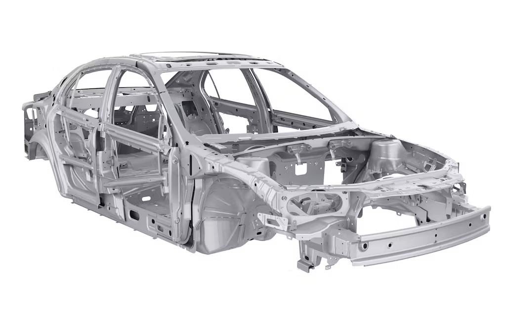
Example of a Unibody Construction
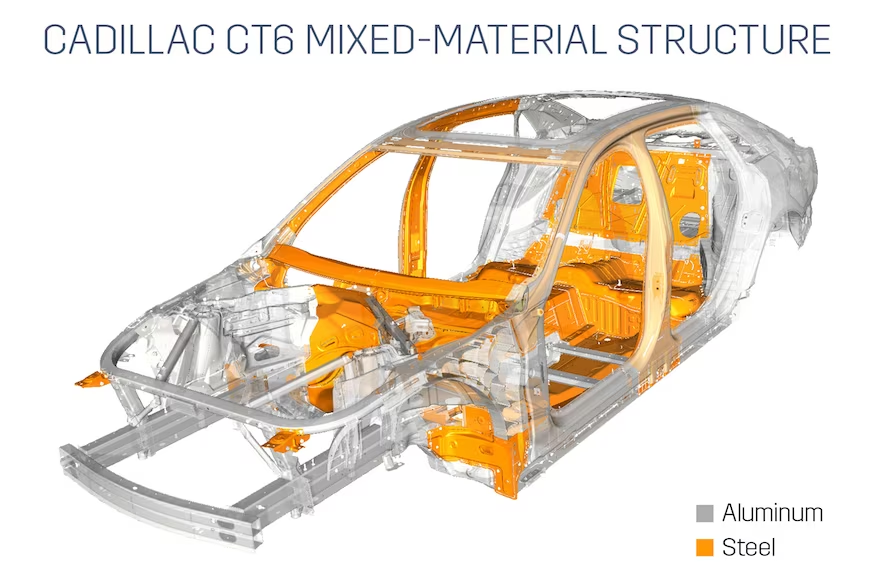
In the unibody construction, the body and frame are integrated into a single unit. This structure, sometimes referred to as a monocoque, is assembled from various individual pieces. For instance, in the case of the Cadillac CT6, 13 different materials are meticulously welded, riveted, and screwed together to form its unibody structure.

A notable advantage of this approach is that not all of these components have to be constructed using dense metals like steel. In the pursuit of enhancing efficiency and performance, automakers are increasingly incorporating lightweight materials. Importantly, this shift doesn’t compromise safety. Unibody vehicles typically integrate crush zones and other features to divert crash forces away from occupants.
What are bending stress and torsional stress?
Bending stress is induced by a bending moment. The bending moment is the torque that counteracts the tendency of a material to want to deflect. Torsional stress can be defined as the shear stress that results in the “twisting” of an object. Both the bending moment and torsional stress are dependent on part cross-sectional geometry. The maximum bending stress and shear stress are a function of the moment of inertia and polar moment of inertia.
For both torsional and bending stress as you get further from the neutral axis and begin to approach the outer surface of the material, the greater the stress. As a result, when trying to calculate the max stress you want to calculate the distance from the neutral axis to the outermost edge of the part.
What is meant by the modulus of rigidity?
The modulus of rigidity is the ratio of shear stress to shear stress in a part.
Torsional Stress of a unibody vehicle
Unibody construction provides heightened torsional rigidity in contrast to body structure designs. This results in a smoother and more comfortable ride. Since the structure and suspension are seamlessly integrated the structure doesn’t have to deal with twisting forces from the frame. However, this high torsional rigidity that unibody designs have can work against them in off-road and hard work settings.
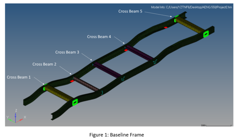
Baseline: Unibody Torsional rigidity and bending stress
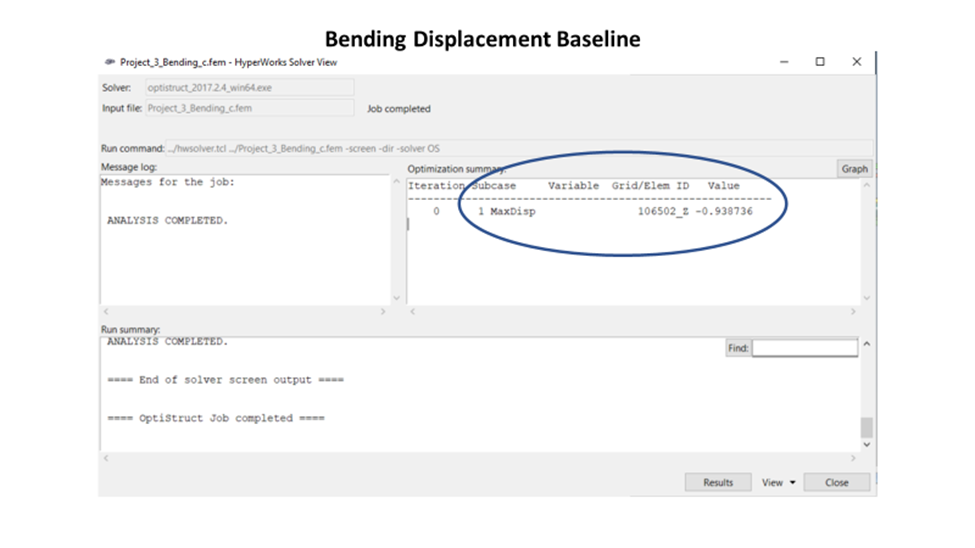
This project aimed to improve the bending and torsional rigidity performance of the unibody vehicle by a minimum of 5%. Two different load cases will be tested during this experiment. The two load cases that were studied were a bending and torsional load case. During the bending load case, a 1000N load was applied on both rockers at the H-Point [ Accelerator Heel Point]. The location of which is 212mm forward of the B pillar. During this test all shock towers were constrained by 6 degrees of freedom, thus causing the body to fold. See Figure 1: Bending Baseline below.

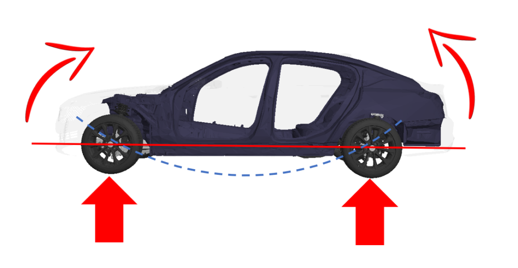
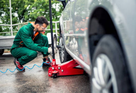
During the torsional stress load case, a 1,356,000 Nmm moment was applied at the front shock towers. The driver’s side shock tower had the load applied down while the passenger’s side had the load applied up. This generated a couple, while the two rear shock towers were fully constrained. As a result, the body would twist upon itself. This load case represents the vehicle driving on uneven roads or being lifted/ jacked up. The stiffness of the body structures was determined based on the displacement of the body structure after the load was applied. The analysis of the project was done using HyperMesh and OptiStruct.
Baseline Results: Unibody Bending
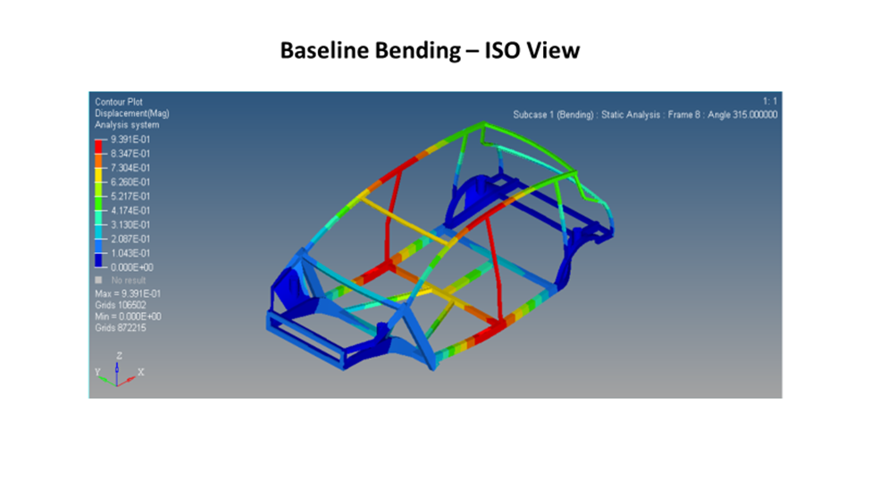
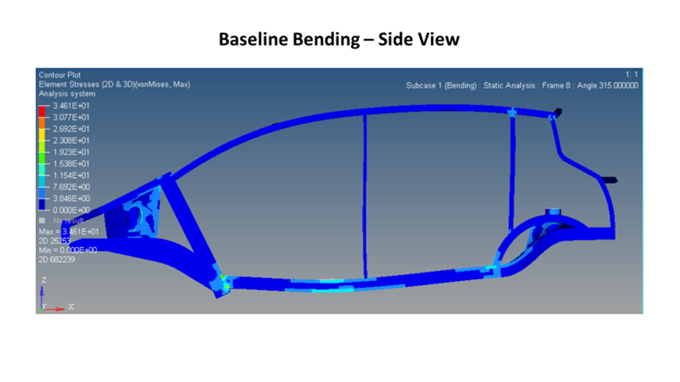
From visual inspection, it is easy to see the unibody structure has much room for improvement, particularly in the pillars and roof rails. All these components are crucial load-bearing elements that play a key part in the structural performance of the system. After successfully running the baseline body structure and evaluating the stresses and displacement across the system. It was easy to see where the biggest deficiencies and areas of improvement in the system were under both load cases.
For the bending stress case, you can see high displacement and stress for aft of the B pillar where the load was applied. The small B-pillar also does not do a good job of engaging the roof rail to support distributing the load to improve performance. The fact that there is only a front and rear header in this vehicle also seems to hurt performance as they are too far from the load to help carry any load and provide stiffness to the structure. See Figure 2: Bending Baseline Results below. All the full-size pictures can be seen in the reference section at the end of the report.
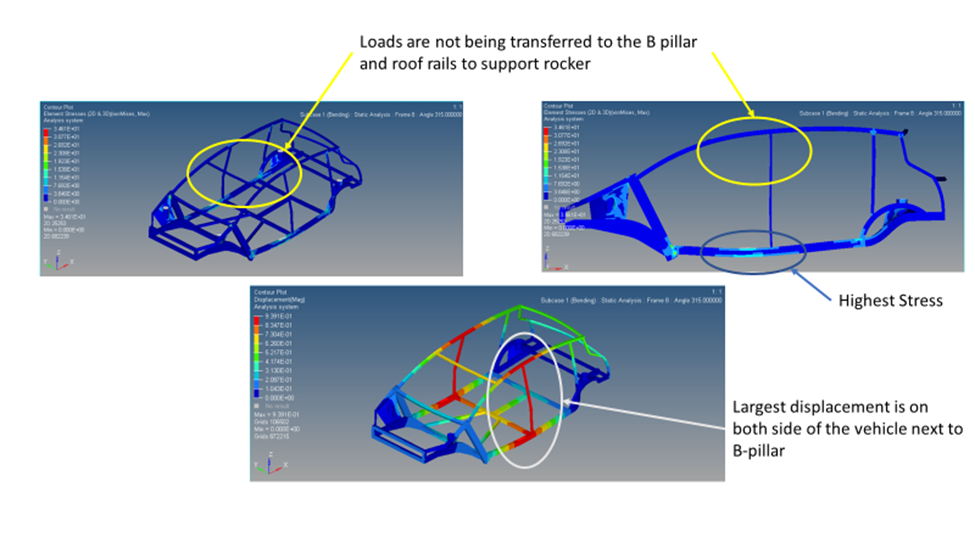
Baseline Results: Unibody Torsional Stress
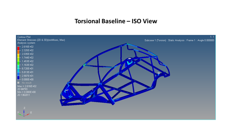
During the torsional load case, significantly higher loads and displacements were noticed at the front of the vehicle, particularly at the front motor rails, A-pillar, roof rails, and front header. The rear of the vehicle being the farthest from where the load was applied was subject to the lowest displacement.
However, the rear of the vehicle still experienced moderate stress because of the vehicle being constrained by the two rear shock towers. Like the bending load case, the B-pillar should play a bigger role in distributing and carrying loads between the upper and lower body structure components but does not due to the small cross-section. The size of the front header also seems to limit how much load can be carried between both sides of the body sides and hinders the performance of the body structure. At the connection between the header and roof ditch, you can also see some of the highest stresses in the entire system. See Figure 3: Torsional Stress Baseline below.

Improving Unibody Torsional and Bending Rigidity:
Automakers are constantly judging the structural performance of a vehicle and its overall mass. Federal requirement continues to become more stringent and demand automakers to fabricate more fuel-efficient vehicles. Forcing automakers to cut out mass wherever possible to maximize fuel economy or range. An ideal engineering solution would meet all performance requirements with the minimum impact on overall vehicle mass.
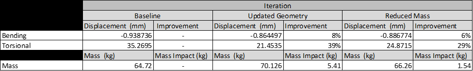
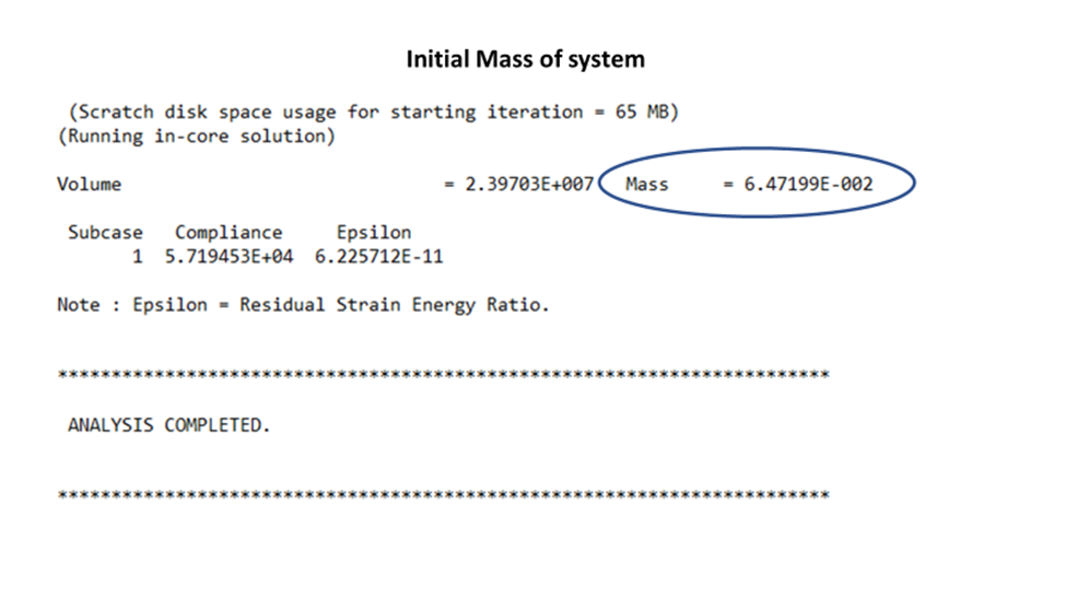
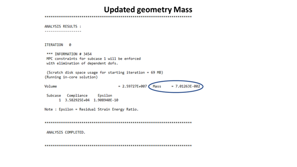
Even though increasing the section or adding additional structural members is great for performance improvements, it hurts the mass of the vehicle. Before any modifications were made, the baseline mass of the body structure was 64.72 kg. After all the updates were complete, the new mass of the structure was 70.12kg, which is a 5.41 kg hit to mass or an 8.35% increase.
Model Modifications
To improve the performance of the overall structure of the vehicle, the two existing components whose section was increased were the front header and the B pillar. Originally, the baseline front header cross section was 40mm x 20mm with a thickness of 3 mm. To improve the performance the cross-section of the front header was increased to 78.82mm x 29.66mm, and the thickness was kept the same. Since the B pillar is one of the most crucial elements in a body structure, the section was increased from 39.67 mm x 19.80mm with a thickness of 3.8mm. To a cross-section of 89.74 mm x 39.66mm, the thickness was also kept the same.
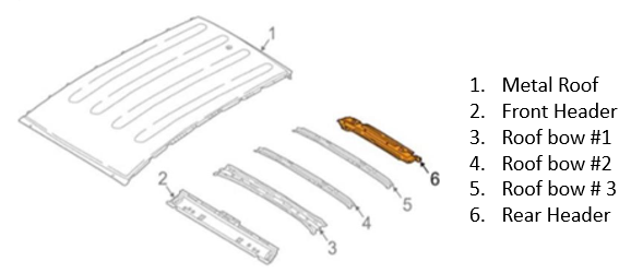
Finally, the last update that was made was the addition of a roof bow above the B pillar, to help transfer the loads between both body sides. The roof bow was made from the same aluminum as the rest of the vehicle to ease assembly. The cross-section of the new roof bow was 69.22 mm x 39.26mm with a thickness of 1.8mm. See Figure 4: Updated Geometry below.

Updated Geometry Results
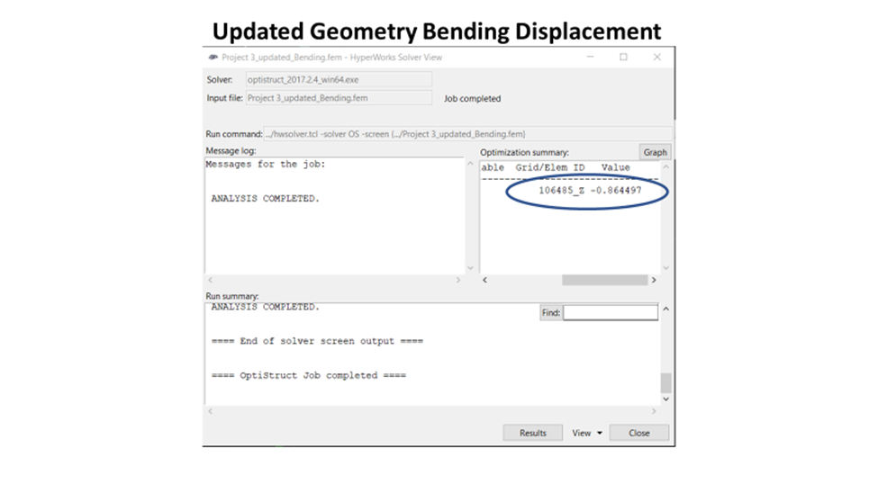
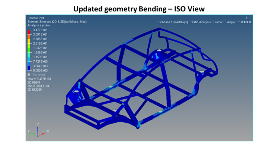
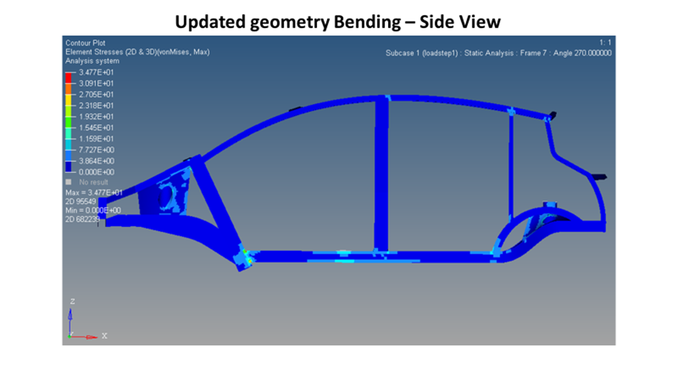
As predicted the updated geometry helps to significantly improve the structural performance of the system. The roof rails were engaged thanks to the increased B pillar section which acts as a primary load path for the system. As the load is being applied to the rocker it begins to pull on the roof rail to stiffen up the body structure and reduce displacement. The addition of the roof bow also helps keep the roof rails from wanting to protrude inboard. See Figure 5: Updated Geometry Bending Below.
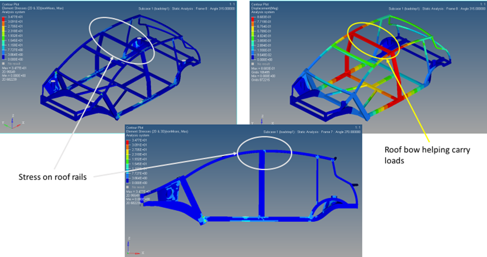
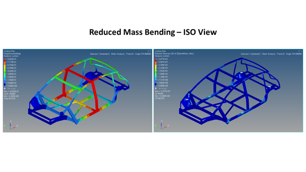
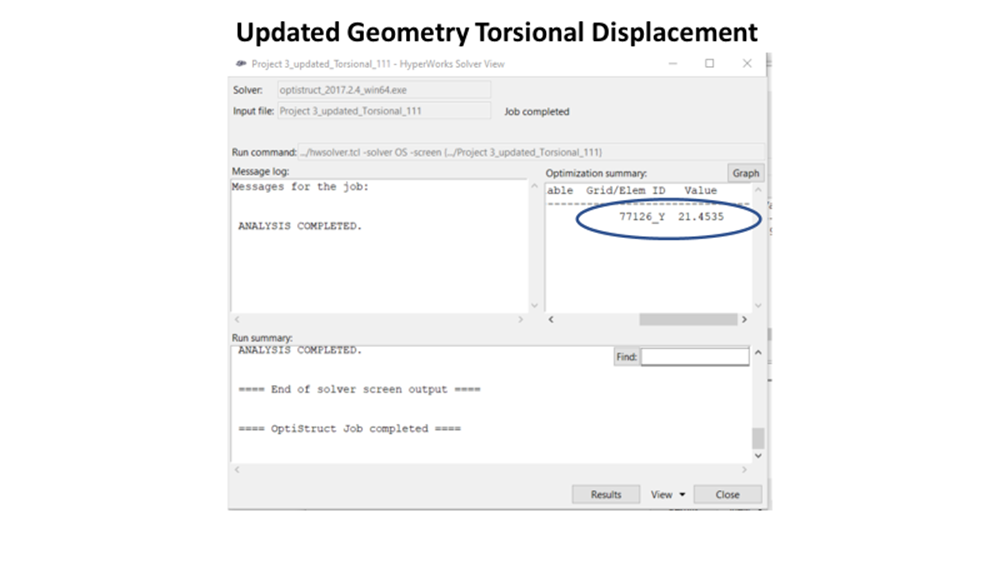
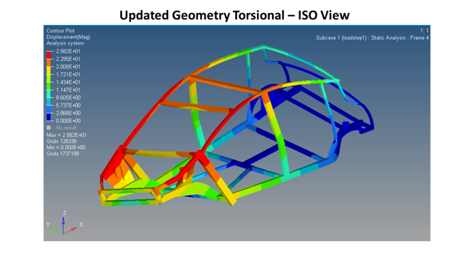
The updated geometry had a more profound effect on the torsional load case, where the increased header section and new roof bow helped to engage more of the B pillar and roof rail. The rear of the vehicle, which previously provided little support with distributing the load across the entire structure, finally began to act more like a load path and as a result, helped stiffen up the complete system. See Figure 6: Updated Geometry Torsional below.

New unibody automotive structure performance:
To reduce the mass impact while still meeting the performance targets, most of the rear cross members of the vehicle were downgauged to 1.5mm. The reason this area of the vehicle was selected to down gauge was that for both load cases, the forces that the rear is subject to are much smaller compared to the front. The result was a minor hit to overall vehicle structural performance with a significant reduction in mass. Even with the down-gauged rear end, we still met our performance targets.
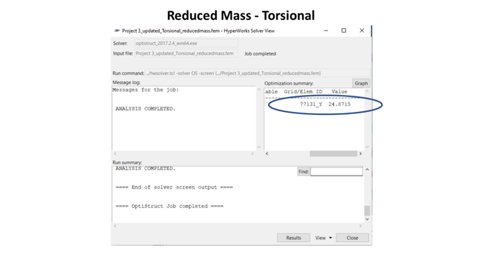
However, the mass of the vehicle was reduced to 66.26kg only a 1.54kg or 2.3% increase from baseline. The HyperView models were omitted from the report because they are extremely similar to the models shown in the previous section, however, they can be found in the reference section at the end of this report.
Conclusion:
In conclusion, trail 2 (updated geometry with the reduced mass) is the most feasible solution set, since we still meet our minimum performance target of increasing the stiffness by 5%, while having a minimal impact on overall vehicle mass. The stiffness for the bending load case on trial 2 was improved by 6% while the stiffness for the torsional load case was improved by 29%.
The reason the torsional load case experienced a more drastic performance improvement had to do with the baseline geometry not being well suited to handle those types of loads. As a result of this minor changes made a big impact on the torsional performance of the body structure. A full list of results can be seen in Table 1: Summary of Results.
Finally, If I had more time to continue iterating and improving my design, my next step would be to focus my efforts on optimizing the rocker, roof rails, and my A-pillar. Key components like this attach to many other components, making updating them difficult and time-consuming. All three components should have their cross-section increased to improve the load path of the system. This would furthermore improve the performance of the body structure which would allow you to reduce the overall gauge of all the components in the system which are currently well over gauged.
Future optimization
Ideally, to optimize this system, you would need to lower the gauge of all the components to no more than 2mm. This update would be more in line with the gauge thickness of aluminum parts in the industry. Taking the system through that drastic mass-cutting exercise would allow you to start with a clean slate and add mass only where the system needs it.
The other area which could be drastically overhauled is the rear end. The size of your rear header, C, and D pillars is grossly undersized. Even though they are not key components in these load cases. After the gauges were reduced on the components at the rear end of the vehicle, the overall structural performance dropped. Indicating that the rear end of the vehicle can still be optimized to improve the structural performance of the system.
Appendix:
Baseline Data: Bending

Baseline Data: Torsional Data


Updated Geometry: Bending

Updated Geometry: Torsional

Reduced Mass Results