Automotive Suspension System 101
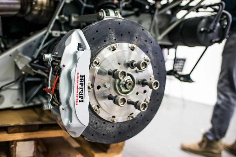
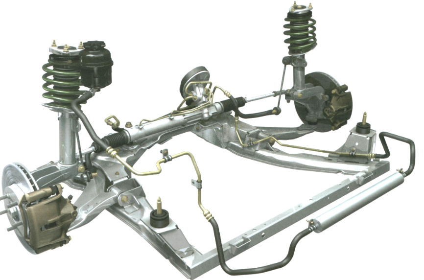
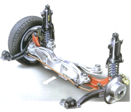
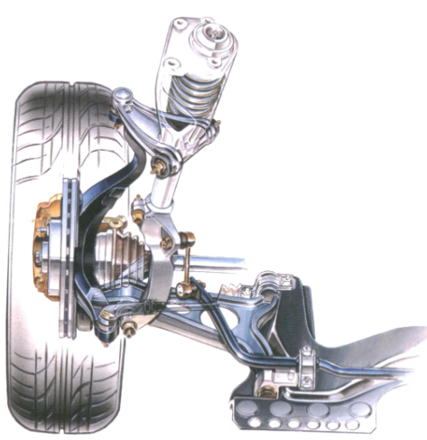
Have you ever wondered how an automotive suspension system is designed? From ATVs (all-terrain vehicles) to locomotives to modern passenger automobiles most types of vehicles that move people from one place to another rely on a suspension system to improve ride quality and comfort. There are a few common types of automotive suspension systems such as leaf springs, pneumatic systems, and hydraulic systems. Automobile suspension systems can also employ various types of springs such as leaf springs, helical coil springs, torsion springs (sway bar), and air springs. A typical coil spring system suspension comprises of many parts such as wheels and tires, springs, shock absorbers (damper), knuckles, and linkages.
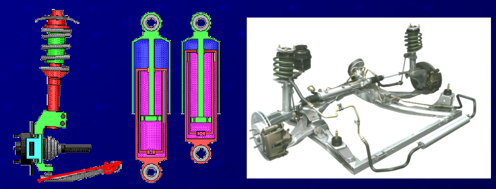
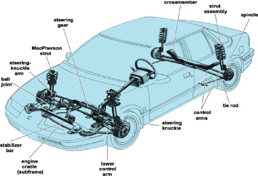
The most common type of suspension system found in modern automobiles is a Macpherson Suspension which is an example of a helical coil springs with a hydraulic dampener. The spring absorbs shocks and stores energy, while the damper, also known as a shock absorber, dissipates this energy. The dampeners/ shocks are usually either hydraulic or pneumatic dampers, with a piston and a rod containing fluid utilized in car suspensions to slow down the motion of the spring. It’s worth noting that the front and rear suspension designs of a car may differ.
Is MacPherson strut suspension good?
Yes, MacPherson strut suspension is a good option for many vehicles. It is cost-effective and makes efficient use of space, which is ideal for compact car designs. MacPherson struts are durable, lasting a long time, and they are less likely to cause damage to other parts when they wear out, provided they are replaced promptly. To ensure optimal performance, it is recommended to check the struts every 50,000 miles to verify they are still functioning efficiently.
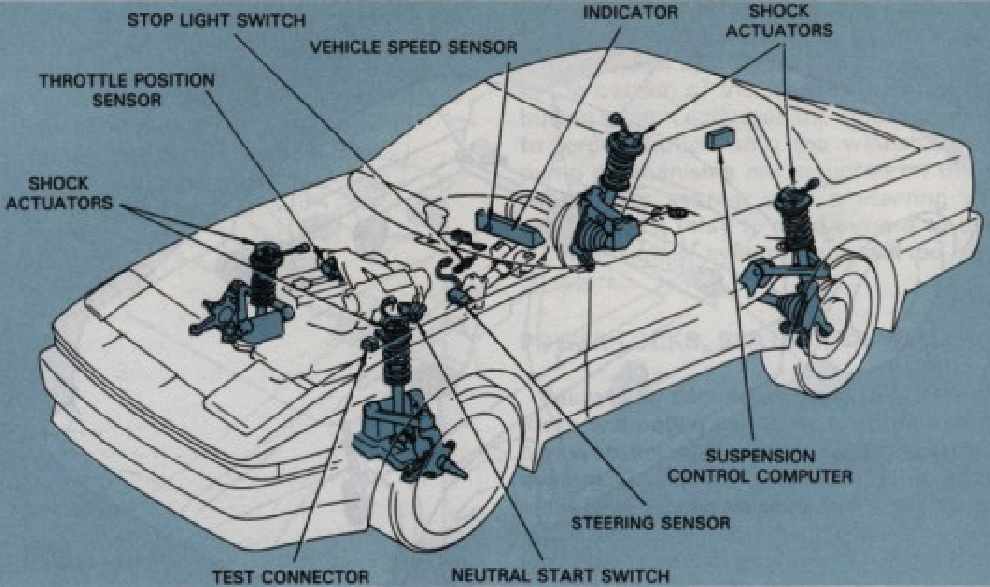
What is an Active Automotive Suspension System
Active suspension systems detect the forces acting on the wheels and continuously modify the mechanical links between the chassis and wheel assemblies. This adjustment aims to maintain the chassis level and efficiently absorb the energy linked to the vertical movement of the wheels.
What is a trailing arm rear suspension?
A trailing arm rear suspension is a rugged and cost-effective suspension design commonly used in vehicles with front-wheel drive. It features two metal links, known as trailing arms, that connect the rear axle to the car’s body. These arms allow the rear axle to move up and down independently while ensuring proper vehicle alignment. Despite their simplicity, trailing arms play a crucial role in the suspension system, providing a good rear packaging design and contributing to the overall performance and stability of the vehicle.
Which forces act on an automotive suspension system?
The primary objective of a suspension system is to shield the vehicle’s passengers from disturbances originating from uneven road surfaces while ensuring consistent contact between the vehicle’s wheels and the road at all times. The suspension system requires special attention during tuning and calibration to maintain the optimal contact between the road wheel and the road surface since all the forces acting on the vehicle are transmitted through the tire contact patches. The forces acting on a vehicle’s suspension system can be categorized into road disturbances and load disturbances.
Road disturbances vary in magnitude and frequency, ranging from high-magnitude, low-frequency disturbances like off-road terrain to small-magnitude, high-frequency disturbances due to imperfections in paved roads. Load disturbances encompass forces resulting from changes in acceleration, braking, and cornering. An effective suspension system should respond smoothly to road disturbances and exhibit robustness against load disturbances.
Why is a suspension system necessary in cars?
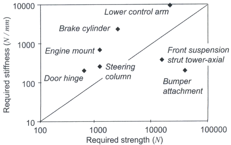
A suspension system wears several hats, such as maximizing overall ride comfort for the vehicle. The suspension system must also maximize the contact between the car’s tires and the road. By maximizing the tire patch, the vehicle will be more stable and experience better handling. A suspension system is designed to meet the following strength and stiffness requirements:
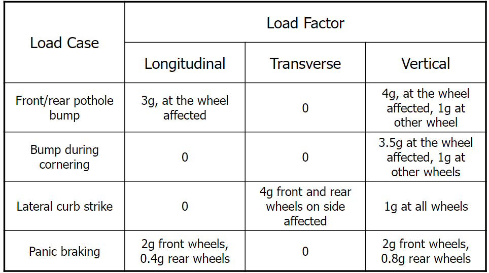
- Strength requirements: braking, cornering, rollover, and vertical bump
- Stiffness requirements: vibration isolation and handling
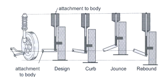
What are the jounce and rebound?
Jounce refers to the upward suspension travel and vertical movement that compresses the spring and shock absorber. A suspension will experience a jounce when a car comes in contact with a bump in the road. Rebound is the opposite of jounce and refers to the downward movement of the vehicle suspension. During rebound, the spring and shock absorber will extend.
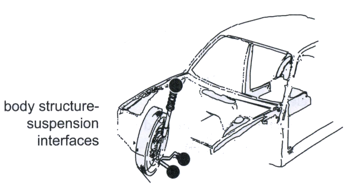
How is an automotive suspension system attached to a car?
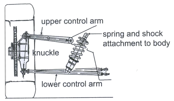
For a coil spring style suspension, the front suspension will attach to the structure (body-in-white) at several points: the shock absorber, spring, and control arms. For a leaf springs style suspension system attach directly to the body-in-white (BIW). In this design, the shock absorber is attached to the clamp that holds the spring to the axle. The goal of the BIW/suspension interfaces is to locate and retain the front suspension in a way that allows the suspension system to function.
Allowable deformation: for all the driving scenarios such as braking, cornering, rollover, and vertical bump. The maximum allowable deformation of the frame/BIW is limited to what can be compensated for by a suspension realignment. Typically, this is about 1-2 mm of permanent deformation in the Body-in-white (BIW) to the suspension interface.

Remembering that all the loads must be in equilibrium, the loads at body structure interfaces can be determined using a free-body diagram of the suspension after the loads at the tire patch have already been found.
What forces act on a resting car?
A car resting on a level road has two forces acting on it, the weight of the vehicle acting at its center of gravity (W) and the normal force or reaction force counteracting gravity at each of the tire patches (Rf and Rr).
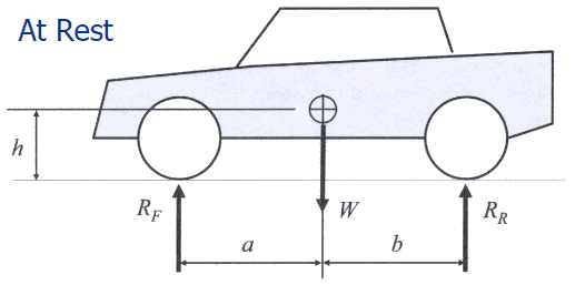
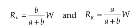
Since the vehicle is at rest, using the static equilibrium equation, the reaction forces at the front, and rear tire patch loads, RF and RR, can be written using the following equations:
How does the Automotive Suspension System react to acceleration and braking?
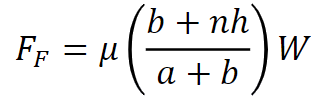
If the vehicle is speeding up or braking the weight of the car will be temporarily altered. Thus varying the suspension positions accordingly. For example, while braking, the load on the front tires (Ff ) can be greater than on the rear tires (Fr). As a result, passengers experience the front dipping down (nose dive) when applying the brakes. The free body diagram can be generated for a steady-state braking deceleration of n times the acceleration due to gravity:

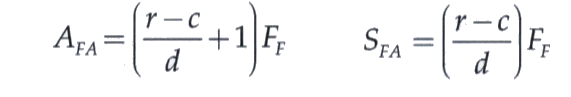
Since the vehicle is assumed to be in equilibrium (steady state braking), it is possible to solve for the Fore-aft tire patch load, Ff.
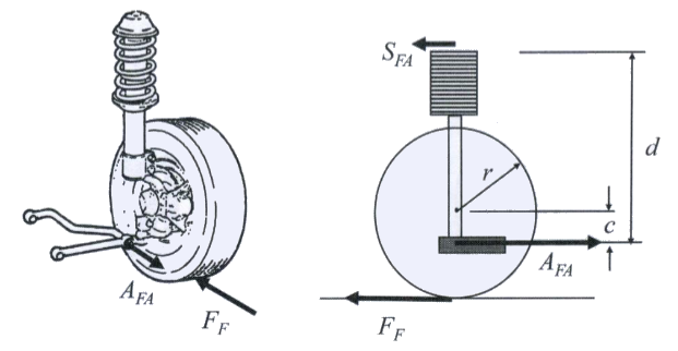
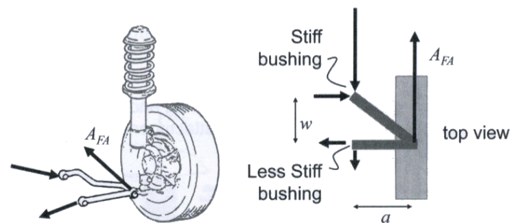
It is then possible to deep dive into this system even further to review the forces that the suspension system is generating on the body structure as a result of braking. Since the fore-aft tire patch load, Ff, was found using a free-body diagram of the whole vehicle, it is possible to find Afa and Sfa. The result will show that predominantly the majority of the loads experienced BIW is transferred through the lower control arm ball joint Afa .
Where:
- Ff = Fore-aft load at a front tire patch
- n = Braking acceleration in g’s
- μ = Coefficient of friction between tire and road
- h = Height of the vehicle’s center of gravity above ground
- Afa = Fore-aft lower control armload at the ball joint
- Sfa = Fore-aft load at the strut attachment
- r = radius of the tire
- c = distance between the center of the wheel and the lower control arm
- d = distance between the lower control arm to the upper body attachment
The reaction forces of the lower control arm ball joint load, Afa at the lower control arm attachment can be seen below.
What happens to the Automotive Suspension System while cornering?
When a vehicle is turning, a centrifugal force acts on the body and pushes it outwards (nW). However, this force is counteracted by the grip between the road and the tires (Li and Lo). As a result, the body rolls about its suspension. However since the suspension system also turns with the car, it is possible to feel the car dip or sway while turning. The free body diagram below can be generated for cornering loads at the tire patch without any load transfer.

Based on the free-body diagram the lateral loads on the tires can be defined with the equations below:
Where:
- Lo = Lateral Load on the outside front tire
- W = Vehicle Weight
- t = Track Width
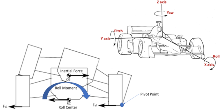
What is a body roll in a car?
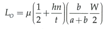
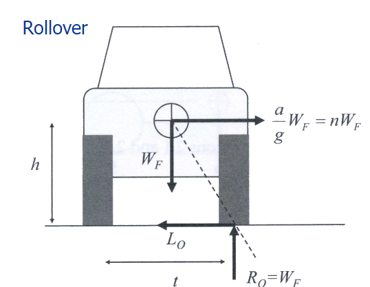
Body roll is defined as the way your car leans to one side during cornering. The higher the vehicle’s center of gravity, the greater the body roll. This is the reason why a pickup truck will experience much more body roll when compared to a small compact sedan. Race cars/sports cars are designed to minimize roll as much as possible since body roll can limit the speed at which one can travel around a corner. Severe under-steer, loss of overall tire grip, loss of mid-corner grip, and letting go suddenly, etc are very dangerous symptoms for a high-performance car. The free body diagram below can be generated for vehicle incipient rollover: outside corner front tire patch load:
Lateral tire patch load, Lo, predominantly through lower control arm attachment, Al . The lower control arm attachment can be seen below.
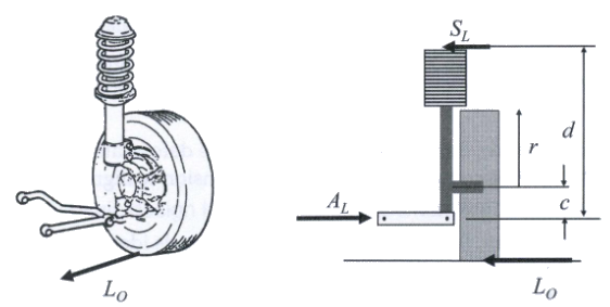
Loads at structure interface: Maximum lateral tire patch load during rollover mode
Where:
- Lo = Lateral Load on the outside front tire
- W = Vehicle Weight
- t = Track Width
- h = Height of the vehicle’s center of gravity above ground
- AL = Lateral lower control armload at the body attachment
- SL = Lateral Load at the strut attachment
- r = radius of the tire
- c = distance between the center of the wheel to the lower control arm
- d = distance between the lower control arm to the upper body attachment
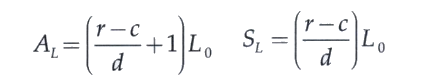
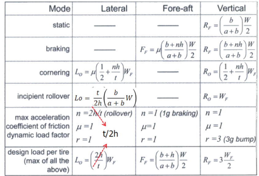
Dynamic load factors
- A design load factor, r, is often applied to account for dynamic effects
- Dynamic design load = rX (static maximum load)
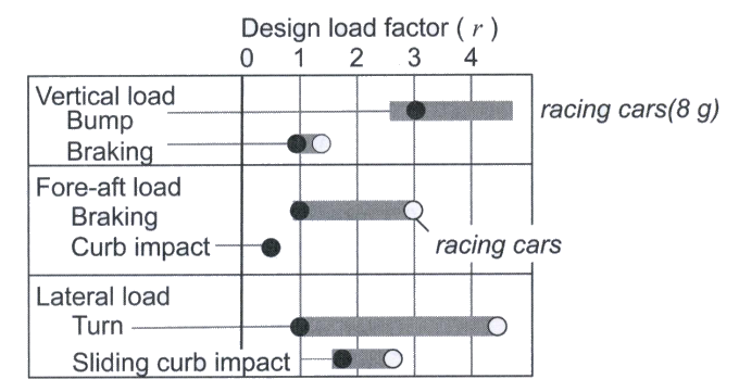
Can speed bumps damage an Automotive Suspension System?
Depending on the speed at which a speed bump or pothole is encountered while driving, the damage that can be done to the vehicle suspension can be significant. Striking a speed bump will force your suspension system into the jounce position, as it tries to absorb the excessive energy. Even if the suspension doesn’t bottom out, you are still placing extra wear and fatigue on the components of the suspension when you hit a speed bump. For example, if the load Rf is high enough, you could blow out a tire, break a coil spring, or a half shaft. The free body diagram below can be generated for vertical tire patch load while driving over a speed bump.
While driving over a speed bump the vertical load, Rf is predominantly counteracted through shock/springs Sv.
where:
- Av= Vertical lower control armload at body attachment
- Sv= Vertical load at the strut attachment
- Rf= Vertical load at the tire patch
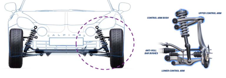
Benefits of a Double wishbone Automotive Suspension System
A double wishbone suspension offers several key benefits, including outstanding road holding and ride comfort, providing excellent stability and a smooth driving experience. It ensures excellent camber control, maintaining better tire contact with the road during turns, which improves handling and performance. The low roll center enhances vehicle stability by reducing body roll during cornering. Although the upper control arm consumes more space within the wheel well, it contributes to the overall effectiveness of the suspension system. Despite being more costly, the superior performance and comfort make the investment worthwhile for many drivers.
Double wishbone suspension Design
Loads at structure interfaces: for different suspension systems (short-and long-arm suspension)
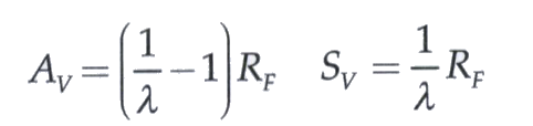
Loads at structure interfaces: for short-and long arm suspension: maximum vertical load at the spring-shock attachment during a bump
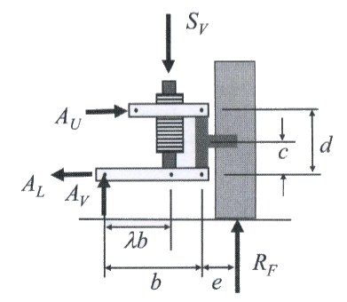
Where:
- Av= Vertical lower control armload at body attachment
- Sv= Vertical load at the strut attachment
- Rf= Vertical load at the tire patch
- λ= Lever ratio for the spring/shock attachment to the lower control arm
Summary of forces act on a suspension system
Example of maximum loads on a front suspension system for a full-size truck.
To calculate the loads acting on the suspension system all the inertial vehicle parameters needed to be collected for the desired vehicle segment. All distance measurements are in meters, and all weights are in newtons.
| | 1988 Chevy C10 | 1987 Ford F150 | 1987 Dodge Ram |
| Wheelbase | 2.985 | 2.959 | 2.78 |
| Height | 1.773 | 1.79 | 2 |
| Height of CG (h) | 0.604 | 0.669 | 0.77 |
| Weight of Vehicle (W) | 18180 | 16885 | 20088 |
| CG to the front wheel (a) | 1.169 | 1.145 | 1.231 |
| CG to rear wheel (b) | 1.816 | 1.814 | 1.549 |
| Track Width (t) | 1.618 | 1.657 | 1.727 |
| Coefficient of Friction (μ) | 0.7 | 0.7 | 0.7 |
| Vertical Static Reaction Forces | 5530.13 | 5175.63 | 5596.46 |
| Braking Acceleration (n) | 1.00 | 1.00 | 1.00 |
| Steady State Braking (Front) | 10317.23 | 9918.15 | 11729.80 |
| Steady State Braking (Rear) | 14738.89 | 14168.79 | 16756.86 |
| Cornering (Front) | 1445.43 | 1463.08 | 1747.02 |
| Cornering (Rear) | 2064.90 | 2090.12 | 2495.74 |
| Roll Over | 14814.16 | 12819.17 | 12552.06 |
| Design Load per Tire (Lateral) | 7407.08 | 6409.58 | 6276.03 |
| Design Load per Tire (For-Aft) | 7369.45 | 7084.40 | 8378.43 |
| Design Load per Tire (Vertical) | 8295.20 | 7763.45 | 8394.69 |

| Mode | Lateral | For-aft | Vertical |
| Static (N) | – | – | 5530.13 |
| Braking (N) | – | 10317.23 | 14738.89 |
| Cornering (N) | 1445.43 | – | 2064.90 |
| Incipient Rollover (N) | 14814.16 | – | 5530.13 |
| Dynamic Load per tire (N) | 7407.08 | 7369.45 | 8295.20 |

| Mode | Lateral | For-aft | Vertical |
| Static (N) | – | – | 5175.63 |
| Braking (N) | – | 9918.15 | 14168.79 |
| Cornering (N) | 1463.08 | – | 2090.12 |
| Incipient Rollover (N) | 12819.17 | – | 5175.63 |
| Dynamic Load per tire (N) | 6409.58 | 7084.40 | 7763.45 |

| Mode | Lateral | For-aft | Vertical |
| Static (N) | – | – | 5596.46 |
| Braking (N) | – | 11729.80 | 16756.86 |
| Cornering (N) | 1747.02 | – | 2495.74 |
| Incipient Rollover (N) | 12552.06 | – | 5596.46 |
| Dynamic Load per tire (N) | 6276.03 | 8378.43 | 8394.69 |