Design of a Fuel Supply System
Background and Theory
The purpose of this design project is to complete a piping system to supply kerosene to 3 burners that each has a different required flow rate. This tank must be 12ft lower than the burners and these burners are located inside the building above. The floor plan is shown below in Figure 1: Basic Floor Plan. Overall all dimensions of the building were given, the Burners can be positioned anywhere in the building, but each burner must maintain at least 6 feet of clearance from walls and other burners. The burner footprint can be approximated as 8ft by 10ft.

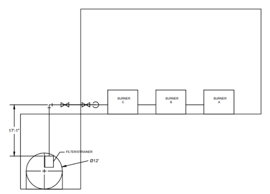
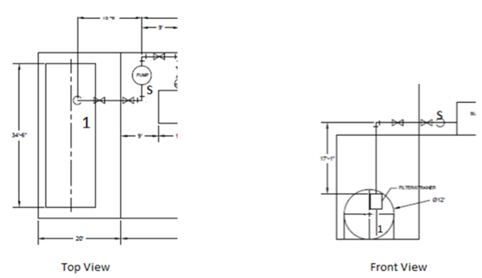
The first step of this design was to complete the pipe layout. This includes all the necessary components, such as valves, strainers, fittings, etc. This layout can be seen below in Figure 2: Top View of pipe layout design and Figure 3: Front View of pipe Layout at the top of the following page. The total system is composed of 1 strainer located at the exit of the tank, 4 90-degree elbows, 2 tees, and 6 ball values 3 of which are used as isolation values while the other 3 are used for regulation, a centrifugal pump placed within the building but as close as possible to the pump, and 3 flow meters (Circles) located right before each of the burners which are used to measure the flow rate into each of the burners.
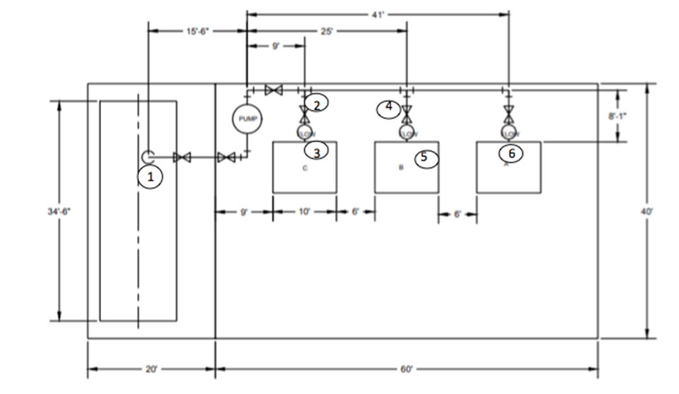
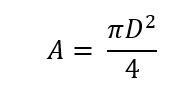
The circled numbers above are in place to assign sections based on volumetric flow. Each section will have its own flow rate and length. These variables are described below. Also, along with this, the estimated diameter for each section can be calculated as well by assuming V=4ft/s (due to the noise and vibration constraint requiring V to be less than 4ft/s for D ≤ 2”). Using the flow rate equation you can solve for the required area see equation 1.
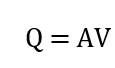
(1)
Where, the volumetric flow rate is Q [ft3/s] and velocity is V [ft/s] are known, and the area is A [ft2]. Once you know the required area you can solve for the diameter using equation 2. Where diameter is D [ft].
(2)
Discussion
The system was designed to make sure that it meets both the noise and vibrations requirements for occupied spaces set forth by ASHRAE HVAC standards [1]. The standard states that for pipes with a diameter less than or equal to 2 inches, the flow velocity should be less than 4ft/s ( V< 4ft/s ). For pipes with a diameter greater than 2 inches, the ratio between the pressure drop and the length of the pipe should be limited to 4 feet of water per 100 ft of pipe length (dP/dL < 4 ftH2O/100ft). The engineering economics of the system was also taken into consideration based on Table 4.11 from the Penoncello textbook, which shows that for economic purposes, the flow velocity should be between 4.7-9.4 ft/s. Also, to avoid erosion, V < 10 ft/s [2]. Listed below are flow rates for each section of the pipe as well as lengths and the pipe selection diameter.
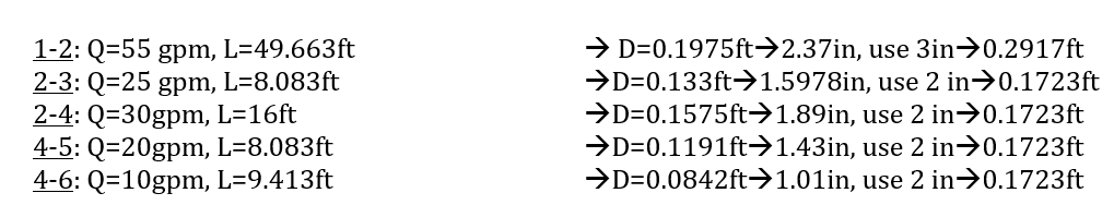
To simplify the system, the majority of the piping will consist of a 2-inch schedule 40. This was done to make the system with fewer fittings/reductions, which results in a less complicated system, so the overall system is easier to assemble as well as easier to order and purchase.
size of the tank
To determine the required size of the tank first, the total flow rate was calculated as 55gpm based on the flow rate requirements for all 3 of the burners in the system (10gpm + 20gpm + 25gpm). Based on the criteria that the system must run for at least six hours continuously, it was determined that the size of the tank would need to be at least 19,800 gallons (55gal/min*60min/1hr*6hours=19,800gal). Because tanks are not sold at that volume, the closest standard-size tank would be a 20,000-gallon tank. The chosen tank is displayed in Figure 4: oil and fuel 20,000- gallon tank and summarized in Table 1: 20,000-gallon tank dimensions on the top of the following page [3].


Valve Selection
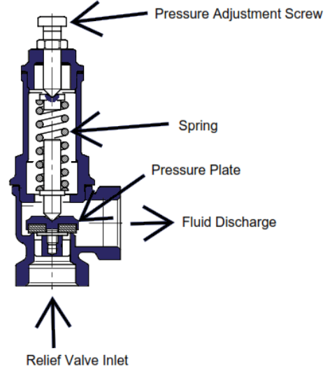
The design also consists of six ball valves, the reason that all ball valves are used was that the ball valve can act as both an isolation valve but it also does a good job acting as a regulation valve. See Figure 5: Ball Valve Schematic below [5].

Consolidating all the valves in the system further simplifies the design of the pipe network. The 3 isolation valves are the 3 valves closest to the pump on the left side of the building, to see them in their respective locations see figure 1 and figure 2 on pages 2 and 3. The purpose of the isolation valve is to isolate certain components of the system in case of maintenance or repair, which is why they were put before and after the pump in addition to right after the tank. The three valves right next to each one of the burner’s primary purposes are to perform flow regulation. To achieve the desired flow rates in each of the burners the resistance through each of the branches must be equivalent, so by partially closing the ball valve, you are able to regulate the flow in each of the branches by altering the resistance through that particular branch. If the flow ever needs to be completely turned off to one of the burners, it can be done by completely closing the ball valve so you are able to isolate the individual burner. There are other forms of flow regulations other than using valves to control the flow. Another option to regulate the flow is with a variable RPM pump, which can alter the rpm of the pump in order to obtain a different flow rate. Increasing the rpm would raise the flow rate and a new operating point would result. Varying the RPM would be more efficient than using valves as flow regulation, unfortunately, it is more expensive. The final method of flow regulation is by varying the impeller diameter inside the pump, unfortunately, that is not easy to do. All options are viable, but a valve regulation would be better suited since the flow can be altered at a specific location, in addition, it would be much cheaper than the other two forms of flow regulation.
EES Code
The EES code used to solve the problem can be found in the appendix. The equations window is set up to solve for sections 1-2, but the varying variables are commented out and defined in the parametric table for each section. For each section, the length, flow rate; diameter, and minor losses change so these variables are manually input. This is a type 3 problem so to be able to solve it you first must guess a diameter and solve the code afterward update guesses and solve again.
The given values are first listed. Since EES does not recognize kerosene as a substance, Dodecane was used because of its similar physical and chemical properties to kerosene. The pipe used is commercial steel, and the surface roughness (ε) was found in Table 3.1 from the Janna text [6]. Before you can solve for the major and minor losses in the system you first must solve for Reynolds Number (Re), see equation 3 at the top of the following page.

(3)
Where d is the pipe diameter [ft], ρ is the density of dodecane [lbm/ft3], V is the fluid velocity [ft/s] and μ is the dodecane dynamic viscosity [lbf/ft3]. The friction factor (ƒ) can be approximated as a function of both the ratio between the surface roughness of the pipe to the diameter of the time as well as the Reynolds Number inside the pipe. This dependence can be seen in the Haaland equation listen below.
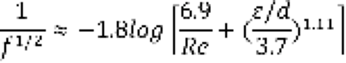
(4)
Where ƒ The friction factor, Re is the Reynolds number, ε is the surface roughness of the pipe [ft] and d is the diameter of the pipe[ft]. Next, the pipe and flow characteristics are solved as normal, as well as the minor losses for each section using either the Janna table [6] or the Crane table [2]. Simplifying the energy equation you get that the pressure losses for each section are found using the minor and major losses. Adding these two variables will give the total hydraulic head loss, which can be used in each section to find the total head loss to obtain the system curve. See the simplified energy equation below, assumptions made with the energy equation are that P1 = 0, V1 = 0 because state 1 is at the bottom of the large tank so the velocity and pressure inside are negligible. Because state 1 is inside the tank that also means that Z1 = 0. Because all 3 branches must have the same resistance than state 2 will be picked right before you get to burner C. there the energy equation becomes,

(5)
Where ∆Hpump is the hydraulic head [ft], ∆Z is the change of height from state 1 to state 2 [ft], V is the fluid velocity [ft/s], g is the gravitational constant [ft/s2], L is the length of the pipe in [ft], d is the diameter of the pipe[ft] and ∑Kloss is the sum of the minor losses in the system. Once you calculate the hydraulic head and the flow rate that the pump must deliver you can use this information to select a pump. The pump selected was the 2x2x7 B&G series 80 in-line pump. See Figure 6: B&G Series 80-SC In-line Pump at the top of the following page.
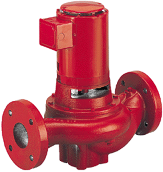
| Pump Name | Specifications |
| B&G Series 80-SC In-line Pump | 2x2x7 @ 1150rpm |
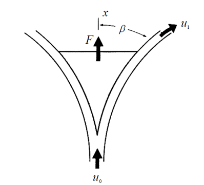
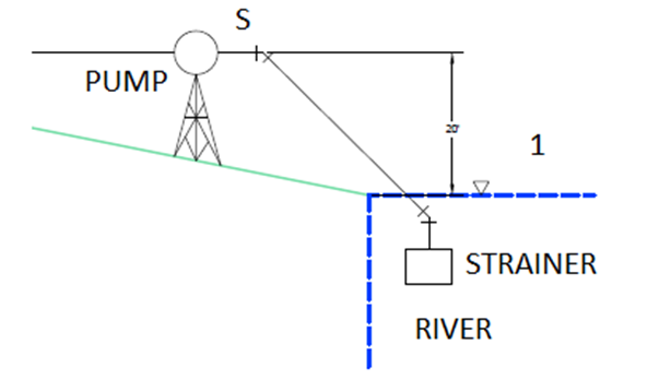
Due to the fact that this is an open system you must check for cavitation. To check for cavitation, the energy equation must be written from the bottom of the tank (1) until right before the pump(s) see Figure 7: Cavitation Check. The assumptions made with the energy equation were that the velocity inside the tank was zero and the pressure is zero. The minor and major losses will be different from the minor and major losses for the system as we are only looking at a section of the pipeline. The calculated pressure right before the pump will be in gauge pressure and to calculate cavitation it will need to be converted to absolute pressure.
NPSHR is read directly from the pump curve, which is the required head for the specific pump at the desired flow rate (4ft). The available head must be greater than the required head to avoid cavitation. See equation 6.

(6)
Where Ppump is the absolute pressure right before the pump, Pv is the vapor pressure of the kerosene and γ is the specific weight of the kerosene. NPSHA must be greater than NPSHR+3ft to avoid cavitation in the system. Once NPSHA and NPSHR have been determined it is possible to determine the max height of the pump before cavitation occurs using.

(7)
To plot the system curve and the pump curve for the system the first step was to replicate the pump curve. To do this, four different points were selected from the pump curve of a pump that we pre-selected (B&G Series 80-SC) and tabulated in an array. From this, the equation of the line was approximated using the form Hp_pump = a0 +a1*v_dot^3 where a0 and a1 are constants. To determine the system curve, the initial point of (0,0), and the operating point were selected. From this, an equation was approximated by the form Hp_system = a0*v_dot^2 where a0 was a constant. The intersection point between the pump and the system curve is the operating point. This can be seen in Figure 8: pump and system curve and Figure 9: pump curve on the following page. The overlapping point is also shown on the pump curve to determine the operating conditions. This is shown below as well.
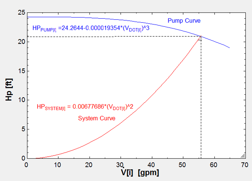
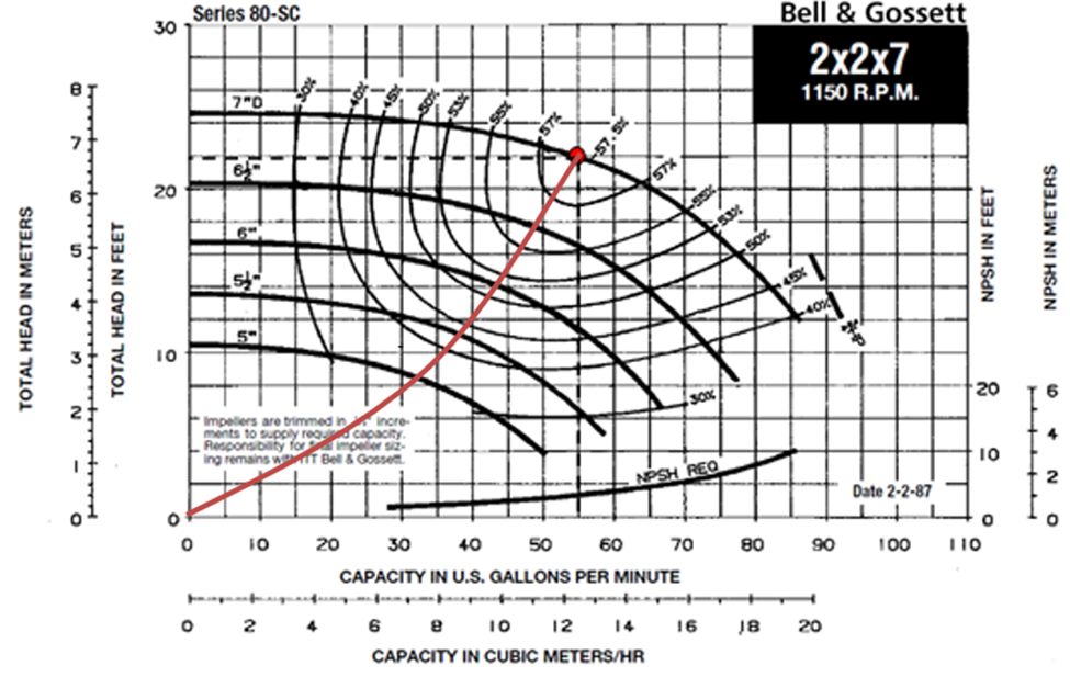
At this point, the volumetric flow rate is 55gpm, and the total head is 22ft. Reading from the chart gives an efficiency of 58%, and shaft power of around 3/4HP. Since kerosene is being used rather than water, the new shaft power is equal to the old multiplied by the specific gravity of kerosene. This results with: W_dot_new=W_dot_old*(ρkerosene/ρwater)= ¾ * (0.81/ 1)= 0.6075HP.
Sources
1) Heating, Ventilating, and Air Conditioning: Analysis and Design, Faye C McQuiston and Jerald D. Parker 1976
2) Thermal Energy Systems: Design and Analysis 1st Edition by Steven G. Penoncello 2015
3) https://www.engineeringtoolbox.com/fuel-oil-storage-tanks-dimensions-d_1585.html
4) http://bellgossett.com/historical-archive/pumps-circulators-archived/series-80/
5) http://threewayballvalve.com/
6) Design of Fluid Thermal Systems, William S Janna