Design of a Power Plant Cooling System
Background
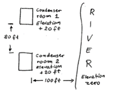
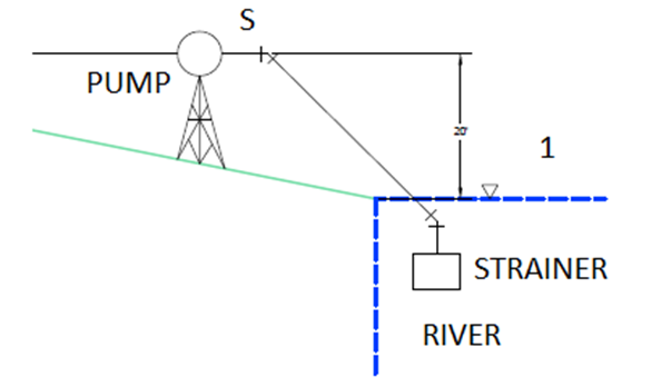
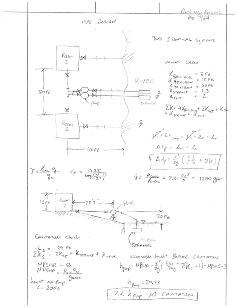
The purpose of this design project is to design a cooling system for a power plant, which includes designing a heat exchanger and a piping system from the river to the condenser to cool the superheated steam from the Rankine cycle. The Rankine cycle produces 1.4MW of power from the steam turbine. The average pressure of the condenser is 10 psi. The condenser rooms are located 20ft above the river and both rooms are 100 ft to the left of the river. The rooms are located 80 ft apart from each other. The layout of the area is shown below in Figure 1: Basic layout. Overall all dimensions of the building were given as 25’ x 15’ x 12’, each condenser room will be cooling separate and independent ranking cycles for the powerplant. Due to environmental constraints, the maximum allowable increase of temperate of the river water is 25F. The temperature of the river water was assumed at 45F, which is the average temperature of the water during winter in the state of Virginia [1].
Based on the design constraints due to the position of each of the condenser rooms relative to the river as well as to each other, a basic cooling system was sketched up. Due to the fact that each of the condenser rooms will be cooling steam from separate Rankine cycles, it was determined to keep the cooling system for each of the condenser rooms separate. The benefit of this is if one of the systems is down, the other system can still work because the cooling system would not be dependent on one another. See Figure 2: System Layout on the next page.
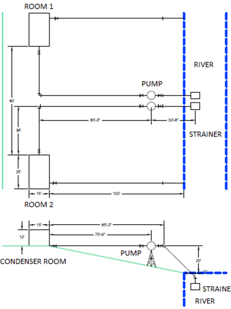
Both systems are identical. Each of the systems is composed of 1 strainer located in the river, 90-degree elbows, 4 ball values which are used as isolation values, three 45-degree elbows, and a centrifugal pump placed as close to the river as possible but at the same level of condenser rooms. A fixture is used to hold up the pump as well as provide support to the piping system.
Thermodynamic Analysis
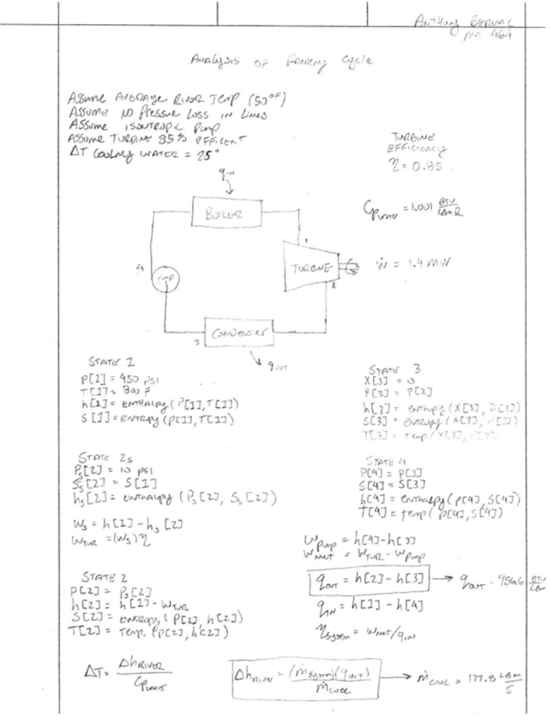
Before it was possible to design the cooling system first a thermodynamic analysis was completed to determine the amount of heat that would need to be removed from the system to convert the steam exiting the turbine back into water see equation 1.

(1)
Where qout is the heat removed from the system per unit mass[Btu/lbm], h[2] is the enthalpy of the system at the entrance of the turbine[Btu/lbm], and h[3] is the enthalpy of the system at the exit of the turbine[Btu/lbm]. Based on the assumed temperature of the river and the max allowable increase in temperature you can find the change in enthalpy of the river, see equation 2.
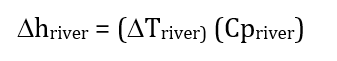
(2)
Where Dhriver is the change in enthalpy of the river [Btu/lbm], DTriver is a known value of 25F based on environmental restrictions and Cpriver is the specific heat of the river water [Btu/lbm-F]. using equations 1 and 2 you are able to solve for the mass flow rate of the cooling water using equation 3.

(3)
Where, m_dot_cooling is the mass flow rate of the cooling water [lbm/s], m_dot_system is the mass flow rate of the Rankine cycle [lbm/s], Dhriver is the change in enthalpy of the river [Btu/lbm] and qout is the heat removed from the system per unit mass[Btu/lbm].
Rankine Cycle
During the thermodynamic analysis, the losses due to the pump were assumed to be negligible while the efficiency of the turbine was assumed at 85% [2]. Any pressure loss in the lines connecting each of the components was also assumed to be negligible. See Figure 3: Rankine Cycle at the top of the following page [3].

Heat Transfer Analysis
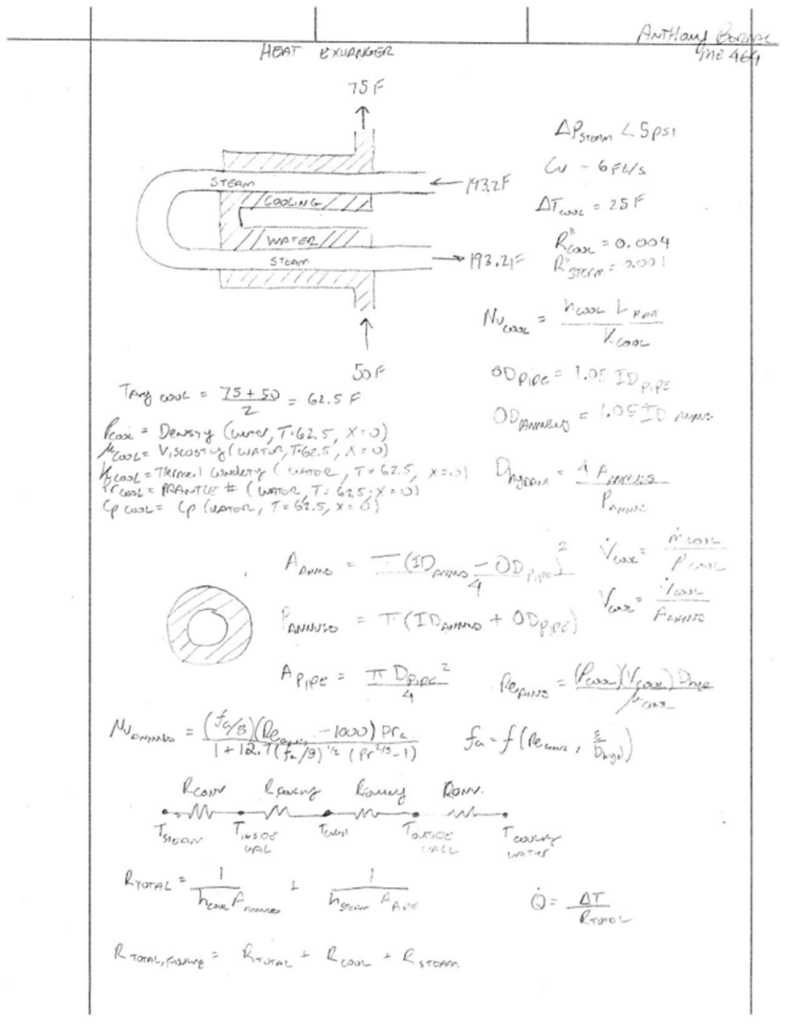
The heat exchanger is to be a hairpin-style heat exchanger with the steam routed through the inner tube while the cooling water is routed through the outer tube (annulus). See Figure 4: basic heat exchanger design below [4].

Due to the fact, that the dimensions of the tube and the annulus are unknown, and the majority of the heat transfer equations are dependent on these variables, to begin the heat transfer analysis the inner diameter of the pipe is assumed to be 0.5 [ft], and the inner diameter of the annulus is assumed at 0.8[ft]. To reduce the number of equations also instead of assuming an outer diameter for the tube it was assumed that ODpipe = 1.05IDpipe that way two of the unknown variables were removed. Using the assumed diameters, you can determine the area of the tube and the annulus, because the area of the annulus is ring-shaped instead of a perfect circle you need to calculate the hydraulic and equivalent diameter see equation 4.
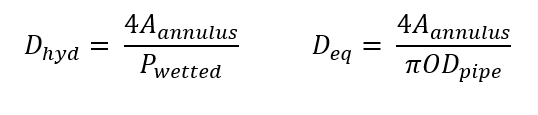
(4)
Where Dhyd is the hydraulic diameter [ft], Deq is the equivalent diameter [ft], Aannulus is the cross-sectional area of the annulus [ft2], Pwetted is the wetted perimeter of the annulus and ODpipe is the outer diameter of the pipe [ft]. Using both the hydraulic diameter and the equivalent diameter you can solve for Reynolds Number (Re), see equation 5
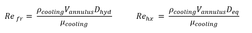
(5)
Where Refr is the frictional Reynolds number, Rehx is the heat exchanger Reynolds number, Dhyd is the hydraulic diameter [ft], Deq is the equivalent diameter [ft], ρcooling is the density of the cooling water [lbm/ft3], Vannulus is the fluid velocity inside of the annulus [ft/s] and μcooling is the dynamic viscosity of water [lbf/ft3]. Taking the known area of the annulus and the volumetric flow rate, which can be determined using the mass flow rate and density of the cooling water, you can then find the velocity of the cooling water using equation 6.

(6)
Where the volumetric flow rate is [ft3/s] and the velocity of the cooling water is V [ft/s] are known, and the area of the annulus is Aannulus [ft2]. The engineering economics of the system was also taken into consideration based on Table 4.11 from the Penoncello textbook, which shows that for economic purposes, the flow velocity of water should be between 4.7-9.4 ft/s, and to avoid erosion, V < 10 ft/s [5].
Reynolds Number
For the pipe, the material used was copper for its great conductivity, and for the annulus, it was determined that galvanized steel would be used because it does not rust and is relatively inexpensive. The surface roughness (ε) of the annulus was assumed as the average of both the surface roughness of the copper and the steel, the surface roughness for each material was found in Table 3.1 from the Janna text [6]. The friction factor (ƒ) can be approximated as a function of both the ratio between the surface roughness of the pipe to the diameter of the time as well as the Reynolds Number inside the pipe. This dependence can be seen in the Haaland equation listed below.

(7)
Where ƒ is the friction factor, Re is the frictional Reynolds number, ε is the average surface roughness of the annulus [ft] and d is the hydraulic diameter of the annulus[ft].
Nusselt Number
The convection coefficient of the steam inside the tube is determined using a built-in EES function because the steam undergoes a phase change. The cooling water does not undergo any phase, change there for the convection coefficient (h) can be determined using equations 8 and 9.

(8)
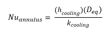
(9)
Nuannulus is the nusselt number of the cooling water inside of the annulus, f is the friction factor, Rehx is the heat Reynolds number, Pr is the prandtl number of the cooling water, hcooling is the convection coefficient of the cooling water [Btu/hr-ft2-R] and kcooling is the convection coefficient of the cooling water. The copper tube is such a good conductor it was assumed that the temperature inside of the tube and outside were the same and as a result, could be neglected. Once the convection coefficient has been determined for both the steam and the cooling water you are able to determine the overall heating coefficient (U) see equation 10 and equation 11 below.
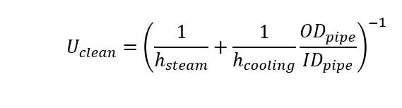
(10)

(11)
Where Uclean is the heating coefficient of the heat exchanger without any fouling [Btu/s-ft2-R] , Ufouling is the heating coefficient of the heat exchanger with fouling taken into account[Btu/s-ft2-R]. ODpipe is the outer diameter of the pipe [ft], IDpipe is the inner diameter of the pipe[ft], hsteam is the convection coefficient for the steam [Btu/hr-ft2-R], hcooling is the convection coefficient of the cooling water [Btu/hr-ft2-R], R”steam is the fouling coefficient for the distilled water inside of the Rankine cycle [hr-ft2-R/Btu] and R”cooling is the fouling coefficient of the river water [hr-ft2-R/Btu]. Using the NTU method it is possible to determine the surface area for each heat exchanger to transfer the required heat from the super-heated steam to the river water. By having surface area, you are able to find the required length of the heat exchanger. By performing these calculations, it is easy to see that having a system without fouling is not reasonable as the required length for this heat exchanger would be 64 ft. This system is being designed for 10 years of operation and even though there might not be any fouling at first it is inevitable that settlement would begin to deposit in the pipe causing additional thermal resistance. See equations 12 and 13 at the top of the following page.

(12)

(13)
Where Ufouling is the heating coefficient of the heat exchanger with fouling taken into account[Btu/s-ft2-R]. Asur is the surface area of the outside of the copper pipe [ft2], is the product of the mass flow rate of the cooling water and the specific heat of the cooling water [Btu/s-R], L is the required length of the heat exchanger [ft]. Once the length of the heat exchanger is known it is possible to determine the pressure loss in both the pipe and the annulus. Similar to with finding the convection coefficient of the steam because of the multiphase you have to use the EES function to determine the pressure loss in the pipe. To determine the pressure loss inside of the annulus, see equation 14.
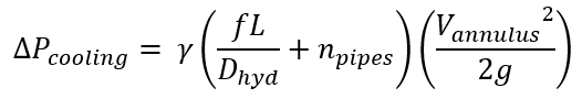
(14)
Where delta_P_Cooling is the pressure drop in the annulus, g is the specific weight of the cooling water [lbf/ft3], npipes is the number of hairpins inside of the condenser room, and g is the gravitational constant [ ft/s2]. After doing some iteration it is possible to determine that the inner diameter of the pipe cannot be lower than 0.45 ft or the pressure loss inside of the pipe will be greater than the 5psi allowable. As a result, a copper 6” type M pipe was selected as it has an ID greater than 0.45 ft but it is not much bigger. With the pipe selected the annulus was selected to try to optimize the system. To do this a parametric study was conducted where the inner diameter of the annulus ranged from 0.6 ft up to 1.5 ft. what was observed from this study was that the best inner diameter for the annulus would be around 1.14ft. There for a 14” Sch 30 steel pipe was selected for the annulus. These pipe selections allow for a minimization of the cost function which is based on the initial and operating cost of the system. In addition, both, the pressure loss in both the annulus and pipe are within specifications see Table 1: Parametric Study below.

Fluid Dynamic Analysis
The final part of the project consists of evaluating the head loss in the system as well as making sure there is no cavitation. Because both state 1 and state 2 are assumed to be at the surface of the river it is possible to simplify the energy equation, to get that the hydraulic head required by the pump to run the system is equal to the minor and major losses. This simplification can be done because of the following assumptions P1 = P2 = 0 , V1 = V2 = 0 and Z1 = Z2 =0. See equation 15 below.
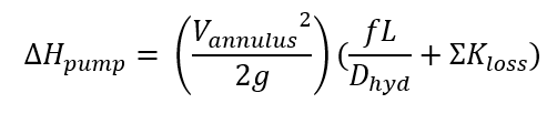
(15)
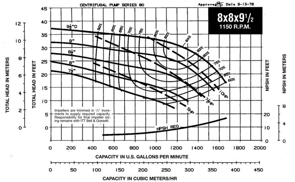
Where ∆Hpump is the hydraulic head [ft], V is the fluid velocity inside of the annulus [ft/s], g is the gravitational constant [ft/s2], L is the length of the heat exchanger in [ft], ∑Kloss is the sum of the minor losses in the system. Once you calculate the hydraulic head and the flow rate that the pump must deliver you can use this information to select a pump. The pump selected was the 8x8x9.5 B&G series 80 in-line pump. See Figure 4: B&G Series 80-SC In-line Pump below [6].
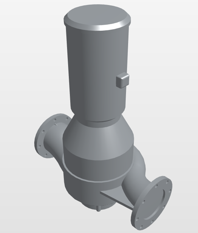
| Pump Name | Specifications |
| B&G Series 80-SC In-line Pump | 8x8x9.5 @ 1150rpm |
Due to the fact that this is an open system you must check for cavitation. To check for cavitation, the energy equation must be written from the open surface on top of the river ( state 1) until right before the pump( state s) see Figure 6: Cavitation Check. The assumptions made with the energy equation were that the velocity in the river was zero and the pressure is zero. The minor and major losses will be different from the minor and major losses for the system as we are only looking at a section of the pipeline. The calculated pressure right before the pump will be in gauge pressure and to calculate cavitation it will need to be converted to absolute pressure.
NPSHR is read directly from the pump curve, which is the required head for the specific pump at the desired flow rate 1200 gpm (9ft) See Figure 7: pump curve below [5].
Conclusion
The available head must be greater than the required head to avoid cavitation. To determine the available head, see equation 16 below. NPSHA must be greater than NPSHR+3ft to avoid cavitation in the system.

(16)
Where Ppump is the absolute pressure right before the pump [psi], Pv is the vapor pressure of the cooling water [psi] and γ is the specific weight of cooling water [lbf/ft3]. Once NPSHA and NPSHR have been determined it is possible to determine the max height of the pump before cavitation occurs using see equation 17 below.
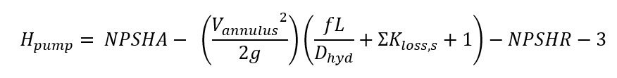
(17)
After calculating the max allowable height for the pump (20.72 ft) it is safe to say that no cavitation will occur at the location in which the pump was placed in the system as the pump is placed 20 ft above the river and the max allowable height is 20.72 ft.
Sources
1) http: //www.surf-forecast.com/breaks/Virginia-Beach/seatemp
2) https: //www.power-eng.com/articles/print/volume-111/issue-6/features/steam-generator-efficiency.html
3) http: //energyeducation.ca/encyclopedia/Rankine_cycle
4) http: //www.enggcyclopedia.com/2011/05/heat-exchanger-types/
5)Thermal Energy Systems: Design and Analysis 1st Edition by Steven G. Penoncello 2015 6) http: //bellgossett.com/historical-archive/pumps-circulators-archived/series-80/
Appendix
Hand Calculations

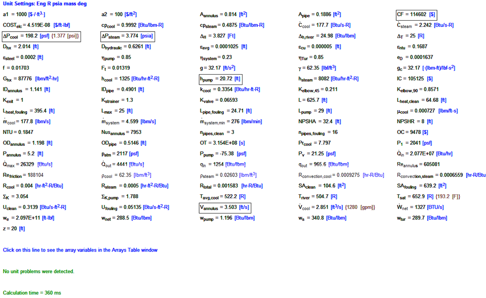
EES Solution: