Air Distribution System Design
Air distribution systems comprise air handlers, ductwork, and related components used for heating, ventilation, and air conditioning in buildings. When designing an air distribution system (air conditioning system) for industrial spaces you should prioritize creating a safe and comfortable environment with minimal health risks for workers.

The indoor climate design of an industrial hall should effectively address air quality and thermal comfort for workers, meeting prescribed design criteria. Additionally, energy-efficient indoor climate targets should be set, typically achieved by minimizing outdoor airflow rates through source control, local ventilation, and efficient space ventilation.
Air Distribution System: Background and Theory
An air distribution system acts as the pathway for conditioned air to move from your HVAC equipment to the spaces inside your building. Typically, they consist of a lengthy network of metal ducts arranged in a manner that allows for efficient air dispersal. When your HVAC system produces heated or cooled air, powerful fans or air handlers blow the air into the ductwork. The air then exits from vents, adjusting the building’s temperature. Return ducts bring air back to the HVAC unit to be filtered, reconditioned, and redistributed.
The design of air distribution systems is influenced by your building’s physical configuration and the available space for installing ductwork. It’s crucial to ensure the ductwork remains in good condition, with all connections tightly sealed, to prevent air leaks and energy loss.
Basis for air conditioning design
When initiating the design of an industrial enclosure, it’s important to outline the intended use by consulting with the building owner and future users.
A scenario for the planned industrial enclosure should be outlined. This scenario should detail:
- the various stages of the flow and batch processes involved in industrial production;
- the space requirements for machinery, tools, work areas, and storage areas for raw materials and products;
- the level of worker involvement required in each stage of the industrial process;
- the heat and contaminant emissions from each stage of the industrial process; and
- the environmental needs for each stage of the industrial process.
The factory scenario should be regularly updated with new information as the design process progresses.
What are the three types of distribution for HVAC systems?
The three types of distribution for HVAC systems are:
(a) Mixing ventilation,
(b) Displacement ventilation,
(c) Diffuse ceiling ventilation.
Air Distribution System Example
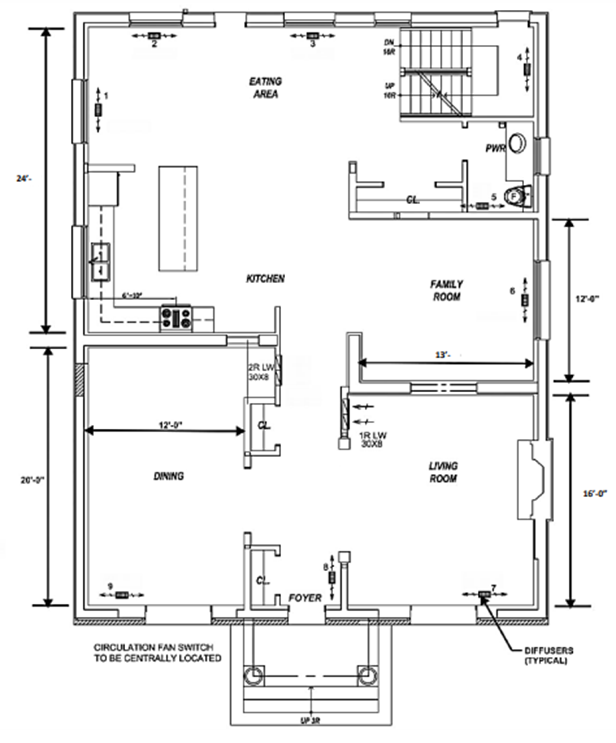
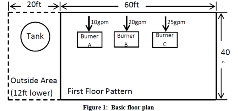
For this example the ductwork system for a given space is shown in Figure 1: The floor plan of the heated space. This design will be based on rectangular ducts that will distribute the total flow rate evenly throughout the entire floor. No return ducts will be supplied and there will be 6 diffusers in total, 1 in each room.
Design Criteria used for example
If there’s no dependable method to circulate heated or cooled air from your furnace, air conditioner, or heat pump, even the most efficient equipment will struggle to maintain a comfortable indoor environment in your residential or commercial building. When designing your project, make sure to plan meticulously for the most effective and efficient air distribution systems. The extra effort you put in at this stage will result in higher energy efficiency and long-term monthly savings throughout the building’s lifespan.
The criteria for this design will be listed in the bullets below:
- The system is restricted to a pressure drop of 0.1 in. wg. per 100ft equivalent length of straight duct.
- Based on the acceptable noise levels in Table 11-1 of the air distribution handout, for a private residence, the acceptable noise criteria are between 25-30 NC.
- The total airflow rate for the entire floor is 1600 cfm.
- The exit of the plenum is located about 6 feet lower than the basement ceiling.
- Due to height restrictions, the duct height cannot exceed 8 inches.
Assumptions
The pressure drop due to the transition of the cross-sectional area between two straight ducts was assumed to be negligible. Also, it is assumed that the intake to the fan is of bellmouth type to reduce pressure losses.
Duct Layout
The initial layout can be seen below with the dimensions and diffuser locations in Figure 2: Duct layout for the given floor. All ducts are made from galvanized steel, the most common duct material. Galvanized steel has a roughness of 0.0005 ft.
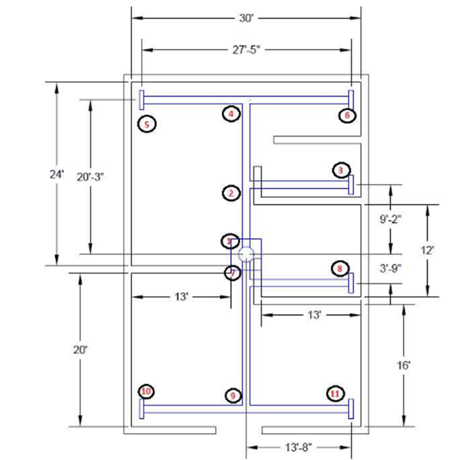
The idea behind the design was to try to make the system as symmetric as possible while getting the airflow to spread out evenly throughout the first floor. All the diffusers are located on the floor and push the air up into the room. There is an elbow located at each of the six diffusers to turn up onto the first floor. The diffusers located at the 4 corners will provide 300CFM of airflow while the 2 ducts in the center will only provide 200CFM.

Figure 2. Duct layout for a given floor
Section Characteristics (including Diffuser selection):
Sections were created from the duct layout according to the chosen flow rates. The flow rates were chosen based on room size and symmetry. The determined sections and corresponding flow rates and lengths are tabulated below in Table 1: Characteristics of each section. Also, based on flow rate and length, the appropriate linear diffuser can be chosen for each section as well.
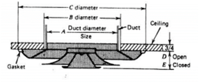
The characteristic of choosing the diffuser is based on the flow rate per linear foot of the diffuser. This will be the flow rate divided by the length. Also, the noise criteria (NC) is based on a 10 ft diffuser, so the NC criteria of 25-30 need to be adjusted accordingly. A schematic of a diffuser can be seen below in Figure 3: Sample Diffuser These values are also tabulated below.
Diffuser
| Run | Section | Flow Rate (cfm) | Length (ft) | Flow Rate/Length (cfm/ft) | Chosen Diffuser Size | NC | NC Correction for Length | Diffuser Loss (in.wg) |
| 1 | 1-2 | 800 | 15.17 | 52.74 | – | – | – | – |
| 2 | 2-3 | 200 | 13.67 | 14.63 | 2 in | – | – | 0.009 |
| 3 | 2-4 | 600 | 11.08 | 54.15 | – | – | – | – |
| 4 | 4-5 | 300 | 13.67 | 21.95 | 2 in. | – | – | 0.009 |
| 5 | 4-6 | 300 | 13.67 | 21.95 | 2 in. | – | – | 0.009 |
| 6 | 1-7 | 800 | 9.75 | 82.05 | – | – | – | – |
| 7 | 7-8 | 200 | 13.67 | 14.63 | 2 in. | – | – | 0.009 |
| 8 | 7-9 | 600 | 11.08 | 54.15 | – | – | – | – |
| 9 | 9-10 | 300 | 13.67 | 21.95 | 2 in. | – | – | 0.009 |
| 10 | 9-11 | 300 | 13.67 | 21.95 | 2 in. | – | – | 0.009 |
For each section, the flow rate per length fit the criteria of the 2-inch linear diffuser. Since these values are on the lower side of the performance for this diffuser, the NC value is negligible for all sections.
EES Results
Running the code to iterate to solve for D gives the diameter for each section with a pressure loss of 0.001 in.wg/ft. Also, the velocity for each section can be found. When picking the dimensions of the square duct from the calculated round diameter, the estimated round diameter must be rounded up or down to choose the dimensions from the appropriate chart. These are also shown at the top of the following page in Table 2: EES Results for each section along with the chosen dimensions
| Section | V (fpm) | D (in) | Selected D (in) | Chosen Dimensions (in x in) |
| 1-2 | 913.8 | 12.67 | 12.9 | 8 x 18 |
| 2-3 | 645.3 | 7.538 | 7.5 | 6 x 8 |
| 2-4 | 850.7 | 11.37 | 11.5 | 8 x 14 |
| 4-5 | 715.0 | 8.771 | 8.8 | 6 x 11 |
| 4-6 | 715.0 | 8.771 | 8.8 | 6 x 11 |
| 1-7 | 913.8 | 12.67 | 12.9 | 8 x 18 |
| 7-8 | 645.3 | 7.538 | 7.5 | 6 x 8 |
| 7-9 | 850.7 | 11.37 | 11.5 | 8 x 14 |
| 9-10 | 715.0 | 8.771 | 8.8 | 6 x 11 |
| 9-11 | 715.0 | 8.771 | 8.8 | 6 x 11 |
As seen above, all velocities are below the requirement of 1000 fpm. The largest adjusted diameter (12.9 in) results in a velocity of 924.7 fpm, which is also acceptable. Ducts for each section fit the requirement of 8” or less for the height.
Fan Selection:
Choosing the appropriate fan for this system will be dependent on the pressure drop across the longest branch and the total flow rate. The longest branch ranges from the plenum to the point of the longest distance. In this case, this would be from 1-10 (or an equal distance of 1-11). The Equivalent length for this distance would result in the following:
Leq1-10 = (D1-7 * Leentrance) + (D1-7 * Letee,branch) + (D7-9 * Letee, through) + (D9-10 * Letee,branch) + + (D9-10 * Leelbow) + L1-7 + L7-9 + L9-10
Leq1-10 = (1.056ft * 12) + (1.056ft * 40) + (0.9476ft * 12) + (0.7309 * 40) + (0.7309 * 15) + 6 + 20.25 + 13.67 = 144.21 ft
The resulting pressure drop from this length and the pressure drop from the diffuser is as shown:
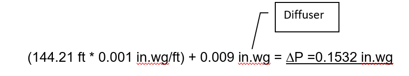
Using ∆P along with the flow rate of 1600 cfm, the proper fan can be selected. Looking at greenheck.com, the proper fan can be the BCF-108 Belt Drive shown below in Figure 4: Chosen Fan [1]. The operating point will be plotted as well.
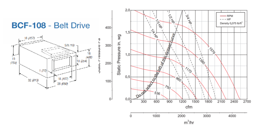
As seen in the above graph, the operating point is around 980 rpm at around 0.40 HP.
Dampers
After the selected fan is chosen, the dampers can now be determined for the system. Dampers are required since the fan will be delivering the same, full pressure rated for the longest branch equally to all of the diffusers. A damper will restrict the pressure to whichever branch it is placed.
To determine which diffuser requires a damper, we must calculate the pressure drop from the plenum to each diffuser. This pressure drop is calculated the same way as before when finding the pressure drop for the longest branch. This pressure can be seen below for each of the six diffusers.
Equations
-Leq1-3 = (1.056ft*12) + (1.056ft*40) + (0.6282*40) + (0.6282*15) + 6ft + 9.167ft + 13.67ft
Leq1-3 = 118.3 ft à ∆P1-3 = 118.3ft * 0.001 in.wg/ft + 0.009 = 0.1273 in.wg
-Leq1-5 = (1.056ft*12) + (1.056ft*40) + (0.9476ft*8) + (0.7309*40) + (0.7309*15) + 6ft + 20.25ft + 13.71ftàLeq1-5 =142.6523 ft
à∆P1-5 = 142.6523ft * 0.001inwg/ft + 0.009 = 0.1517 in.wg
-∆P1-6 = ∆P1-5 = 0.1517 in.wg
-Leq1-8 = (1.056ft*12) + (1.056ft*40) + (0.6282*40) + (0.6282*15) + 6ft + 3.75ft + 13.67ft
Leq1-8 = 112.883ft à ∆P1-8 = 112.883ft*0.001in.wg/ft + 0.009 = 0.1218 in.wg
-Leq1-10 = 144.21 ft à ∆P1-10 = ∆P1-10 =0.1532 in.wg (calculated earlier for fan)
∆P1-11 = ∆P1-10 = 0.1532 in.wg
Results
The final results are tabulated below.
| Section | Equivalent Length, Le (ft) | Pressure loss (in.wg) |
| 1-3 | 118.300 | 0.1273 |
| 1-5 | 142.652 | 0.1517 |
| 1-6 | 142.652 | 0.1517 |
| 1-8 | 112.883 | 0.1218 |
| 1-10 | 144.210 | 0.1532 |
| 1-11 | 144.210 | 0.1532 |
Comparing the pressure loss to each diffuser, it can be examined that the value is lower for the shorter branches (sections 1-3 and 1-8). When the fan is in operation, the pressure delivered will be 0.1532 in.wg, or the pressure for the largest branch that it is rated for. To account for this, dampers will need to be placed in those two branches to match the calculated pressures above. For example,
-For sections 1-3, the increase in pressure is 0.1532-0.1273 = 0.0259 in.wg. So, a damper that is rated for 0.0259 in.wg will be placed in sections 2-3.
-For sections 1-8, the increase in pressure is 0.1532-0.1218 = 0.0314 in.wg. So, a damper that is rated for 0.0314 in.wg will be placed in sections 7-8.
The other branches either match this pressure or are slightly different, which makes these negligible.
Conclusion
The designed air distribution system duct layout, using six diffusers, satisfies all requirements. Each section has a pressure loss of 0.001 in.wg/ft along with a velocity lower than 1000 fpm and NC less than 25. Each selected duct height is less than 8 inches. The selected fan is rated to provide the plenum with the required discharge flow rate in the branch of the greatest pressure loss. Two dampers will be required for sections 2-3 and 7-8 to keep the constant pressure loss of 0.001 in.wg/ft.
Source
- Greenheck.com