Design of a Heat Sink
A heat sink also spelled heatsink, is a passive heat exchanger that moves heat generated by an electronic or mechanical device to a fluid medium, typically air or a liquid coolant. This process helps dissipate the heat away from the device, allowing for temperature regulation. Heat sinks are commonly used in computers to cool CPUs, GPUs, chipsets, and RAM modules. They are also utilized with high-power semiconductor devices like power transistors, as well as optoelectronics such as lasers and LEDs when the component’s heat dissipation capacity is inadequate for temperature control.
Design of a Heat Sink: Example
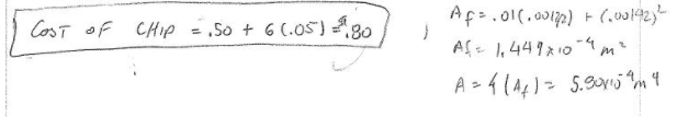
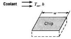
The purpose of this project was to design a heat sink with square fins, which would maximize the heat dissipation from a 1cm x 1cm computer chip. The computer chip will be receiving a power input of 1 watt. The heat sink is going to keep the chip cool through convection using ambient air at 25°C. There is contact resistance between the chip and the heat sink of 1 x 10⁻⁴ m2K/W.
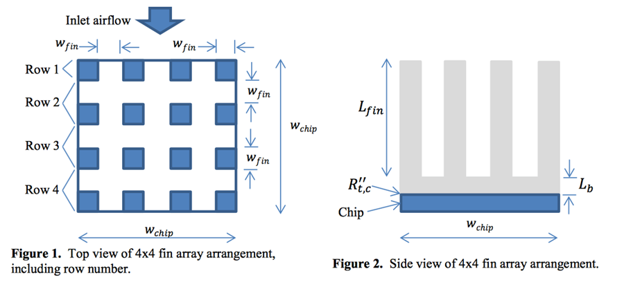
The height of the fins is set at 0.5cm [0.005m]. The width of each of the fins must also be equal to the gaps between each of the finds. Finally, a cost was calculated based on the number of cuts needed to manufacture the heat sink, and the best design was selected. See Figure 1: Top View of 4×4 fin array arrangement and Figure 2: side view of 4×4 fin arrangement below.
Discussion
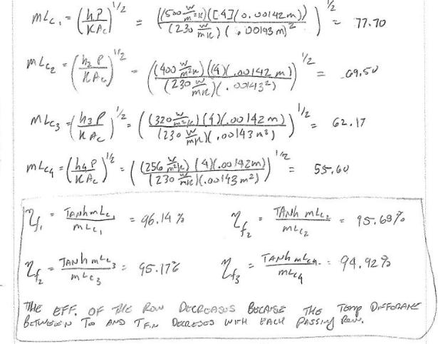
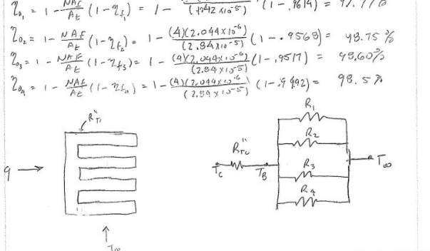
It was observed that as the number of columns of fins increased the overall efficiency would increase thus allowing the temperature of the chip to be greater. To determine the temperature of the chip equation 1 was used.
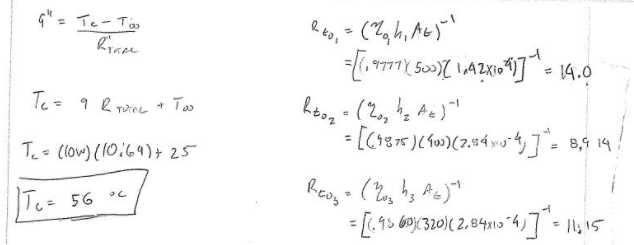
TChip = T∞ + (qchip)(Rtot) (1)
Where T∞ is equal to the temperature of the ambient air, 25[°C], qchip is equal to the electrical power being supplied to the chip, which is equal to 1[W], and Rtot is equal to the total thermal resistance of the chip [k/W]. This data was then plotted and a correlation of exponential decay was found between the number of fins and the temperature of the chip.
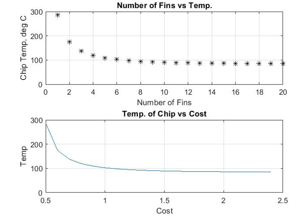
The relationship that was found was that as the number of fins increased the overall temperature of the chip decreased. With each additional layer of fins, the improvement was decreased and by the time that the number of fins was increased to over 14 fins, the temperature bottoms our around 84°C. See Figure 1: Number of fins vs Temp below & Cost.
Conclusion
If it is desired for the temperature of the chip to be below 115 °C I would recommend having a design of 5×5. The reason I would choose 5 fins is because this is the least number of fins required which has a temperature which is below 115 °C. And as seen on the bottom graph of Figure 1 the less number of fins on the heat sink the lower the cost. As stated above the minimum temperature found for this heat sink would be around 84 °C.
Hand Calculations