Roll Control System Simulation
This simulation is of a vehicle performing a cornering maneuver. During a cornering maneuver, the rolling motion or roll angle which is felt in the vehicle about the x-axis is a result of the inertial forces acting on the vehicle’s center of gravity and the vertical elasticity of the suspension. The roll axis is the instantaneous center of rotation of the vehicle and is dependent on the chassis geometry. This theoretical axis can be found by calculating the front and rear roll center of the respective front and rear suspension and then connecting these two points.
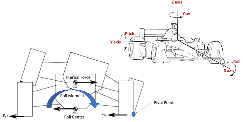
The length of the moment arm combined with the stiffness of the suspension will determine how many rolls a vehicle will experience. The greater the distance between the center gravity of the vehicle and the roll center, the greater the moment the arm is created. A vehicle with a large moment arm is more prone to roll over, such as large SUVs or lifted trucks. As a result, automakers design a vehicle to minimize this moment arm allowing drivers better control of the vehicle during cornering. However, if a driver performs a turn too sharply and/or too fast, then it is possible for the roll angle to begin to increase to the point where the vehicle beings to tip about the pivot point. Depending on how large the roll angle is it can cause the driver to lose complete control of the vehicle. See figure 1: automotive roll movement.
Analysis:
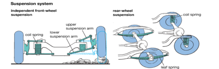
To simplify the analysis, the model only focused on understanding the roll movement of the vehicle. For this project, any pitch or yaw movement of the vehicle will be out of scope. Due to this simplification, the model will assume the roll axis of the vehicle to be fixed and the center of gravity is exactly in the middle of the vehicle. The vehicle will also be modeled as having a basic air spring and dampener suspension system. An air compressor pneumatically controls most commercial air springs found in the vast majority of production vehicles. However, to simplify our suspension system, our air spring will be directly controlled using an electric motor. The rotational motion from the motor will be converted to linear motion via the ball screw and piston. See figure 2: project vehicle model below.
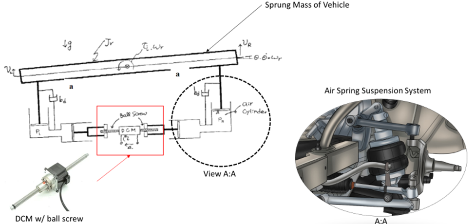
The goal of this project is to design a roll control system that will roll the vehicle quickly back to θ = 0 by incorporating a feedback loop. The controller will use measurements taken from the roll angle, angular velocity, and angular acceleration of the sprung mass to determine the input current into the motor which will balance out the vehicle. To simulate the cornering force experienced by the vehicle an input torque of 2000 N-m will be applied to the center of gravity. A full list of system parameters can be seen below in table 1: system parameters SI units below.

The two main parameters which need to be calculated are the dampening coefficient and the pressure of the air spring. To calculate the air spring pressure, we first must take into account the fact that the total pressure inside of the air spring is going to be equal to the pressure due to gravity and the torque experienced by the vehicle. The total pressure inside the air spring can be found using the following equation.

Where Pinital (N/m2) is equal to the load acting on the piston due to gravity:

Where k (N/m) is equal to the air spring constant which can be found with the following equation (Scribd. (n.d.):
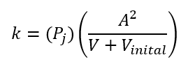
since air is a compressible fluid, we cannot assume the density of the air inside the air spring is constant. As a result, the air springs are modeled as exhibiting nonlinear compressibility. Based on this information; the following equations can be used to calculate the Pj pressure (N/m2) inside the air cylinder:
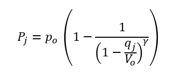
By combining the equations for Pinital and Pj the state variable can be found:
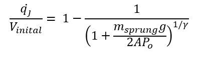
See Table 2: List of Symbols below to view a full list of symbols for all the equations shown above.

Po is the initial pressure which is a known constant at 1.0e5 N/m2. The air inside the air spring is assumed to be composed of an adiabatic gas, thus γ is also a known constant of 1.4. The sprung mass of the vehicle is equal to the total weight of 680.38kg. The second variable which needs to be calculated is the dampening coefficient (bd). The purpose of the dampener is to reduce/slow any movement in the suspension system. The dampening coefficient can be described with the following equations:
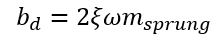
Where the angular frequency ω (rad/s) is equal to:
The natural frequency (fn) is fixed at 1.5Hz and the dampening ratio (ξ) is assumed to be between 0.25 -0.3. During the first part of the results, the dampening ratio will be found.
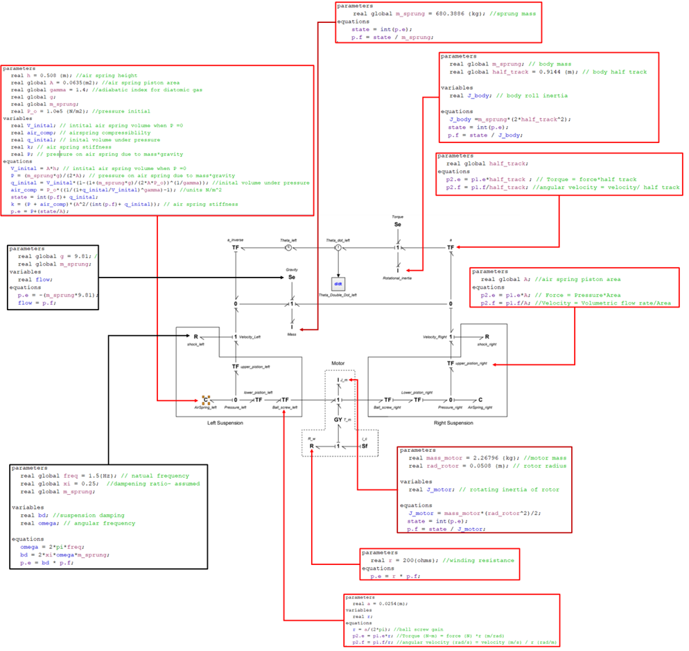
To simplify the bond graph of the system, the system was modeled ask having 3 major components, the motor, the suspension (both left and right side), and the sprung mass. See figure 3: pictorial model and bond graph below.

Figure 3: Pictorial model and bond graph
Starting from the top, the sprung mass was modeled as having two main energy storage elements, the mass of the vehicle and the rotational inertia of the vehicle. Both mass elements were attached to a 1 junction, representing the vertical and angular acceleration felt by the body of the vehicle. These two 1 junctions also had an effort source attached to each one of them, symbolizing gravity and the torque which is applied to the center of gravity of the vehicle. The two main elements in the suspension were a dampening element modeled as a resistor and an air spring modeled as a capacitor element. There are two transformers connecting the suspension to the electrical motor. The first transformer converts the pneumatic pressure in the air spring to a linear force in the piston. The second transformer converts the linear force in the piston to a rotational torque in the ball screw. To create the PID controller an “f” sensor with a derivate and integrate blocks was added inside of the sprung mass part of the bond graph. The integrator block is used to measure the roll angle of the vehicle. The f sensor is used to measure the angular velocity of the vehicle. Finally, the derivate block is used to determine the angular acceleration of the vehicle. Using these three systems inputs the following equation can be used to determine the electric current needed to level out the vehicle as quickly as possible:
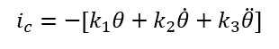
Where k1, k2, and k3 are gain constants that will need to be solved for. The final bond graph with code can be seen below in figure 4: bond graph model with code. To see the full code plus the 20Sims file please see the reference section under the attached files.
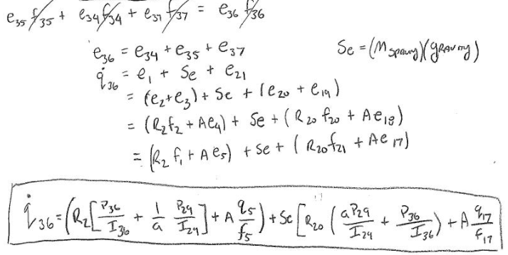
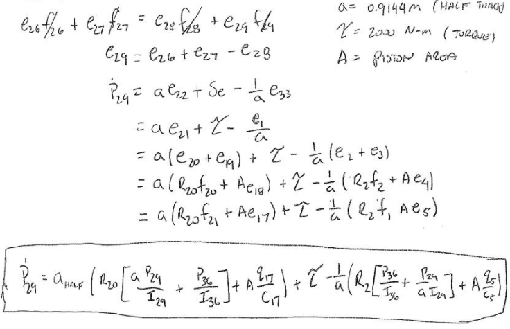
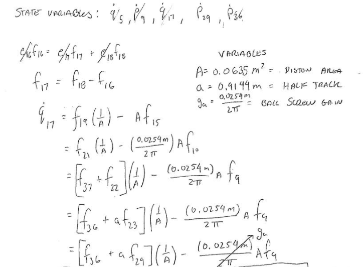
To calculate and solve for the state variables the bond graph was rearranged. There are a total of 5 state variables in the bond graph system one for each I or C element. All 5 state variables are highlighted in yellow in figure 5. To make solving for the state variables easier each bond in the bond graph was numbered from 1 – 37. A full step-by-step breakdown of how each state variable was calculated is attached to the reference section at the end of this report. See figure 5: state variable bond graph at the top of the following page.
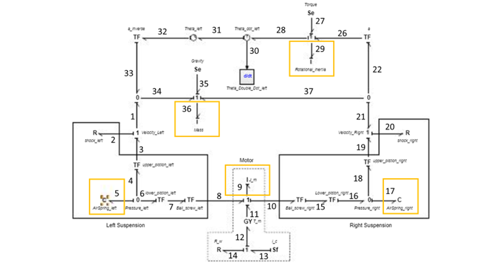
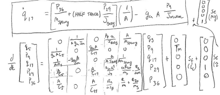
All 5 derived state equations can be seen below:

By rearranging each one of the state equations found above, the state representation in matrix form can be used to mathematically model this system. The purpose of this matrix is to easily show how all the system inputs and output are related by a first-order differential equation. See the state representation matrix below.
Results:
During the first part of this project, you assume that your vehicle is at rest (zero torque) on a perfectly flat road. Therefore, at beginning of the simulation, the only force acting on the system is the force of gravity on the sprung mass. The main purpose of this part of the project is to verify your code is working properly and to find out the value of the dampening ratio (ξ). During this part of the project, the pressure in the air cylinder should be constant since there is no movement of the vehicle. As a result, theta, theta_dot, and theta_double_dot are all equal to zero. See figure 6: vehicle at rest below.

To demine the best value for the dampening ratio, the radius of the motor was changed to 1.0e20 to simulate a motor that cannot be moved. Afterward, the dampening ratio was slowly increased from 0.25 to 0.3 and the response to the graph was observed. To make sure the initial conditions are the best meet it was determined that the dampening ratio should be 0.30.
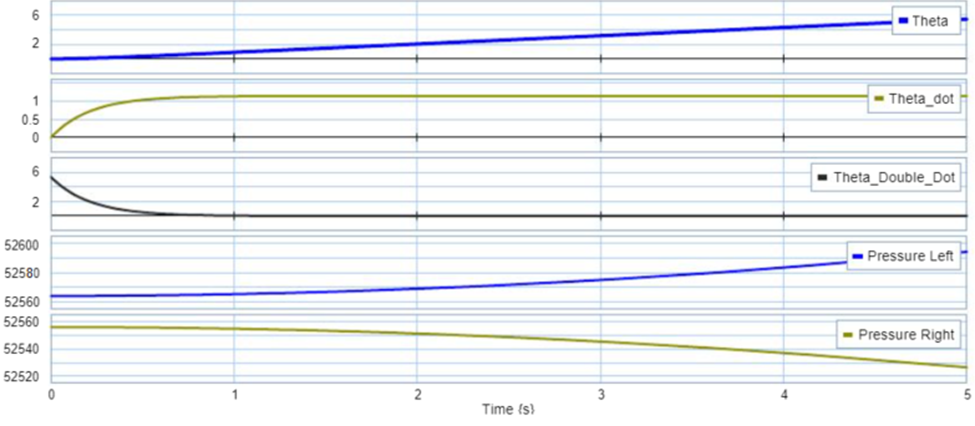
For the second part of this assignment, a cornering force was added 2000N-m. As a result of this update, my roll angle started to increase linearly. My angular velocity reached a max speed of 1 rad/s and afterward leveled out. My angular acceleration started at 6 rad/s2 and quickly decreased down to zero as the system arrived at a steady state. Finally, the pressure on the right started to increase while the pressure on the left began to decrease. The reason behind this is that the left side of the vehicle is being pushed down as the vehicle rolls into the curb, increasing the pressure on the right air spring. Consequently, the right side is lifting reducing the pressure on the left air spring.
Conclusions:
As automakers design vehicles it is crucial that they minimize the distance between the roll center and the center of gravity of the vehicle. Designing the suspension system to minimize this distance it allows the vehicle to reduce the amount of roll that a vehicle experiences and as a result the vehicle will have better handling. The challenge that automakers face is depending on the terrain that the vehicle may be traveling on, the roll center of the vehicle can shift from scenario to scenario. This is the reason automakers incorporate components such as a sway bar into vehicles to help reduce the amount of roll a vehicle will experience. In recent years automakers such as Audi have incorporated electronic systems which vary the amount of torque in a sway bar to keep a vehicle flat around a turn, very similar to what was done with this project. Electric vehicles by nature have a much lower center of gravity due to the giant battery pack on the floor. As a result, they experience less roll than a traditional ICE vehicle, since they have a smaller moment arm. This will make electronic anit-roll components not as critical as it has been in the past.
Hand Calculations: