Thevenin’s theorem: a simple way to simplify complex circuits (and make your life easier)
Have you ever come across those complicated circuits with resistors, voltage sources, and all that jazz? Well, I’m here to tell you about an awesome concept called the Thevenin equivalent circuit, which can simplify those complex circuits into something much easier to understand. It’s like finding the secret recipe to crack open any circuit! So, let’s get started!
What is Thevenin equivalent principle?
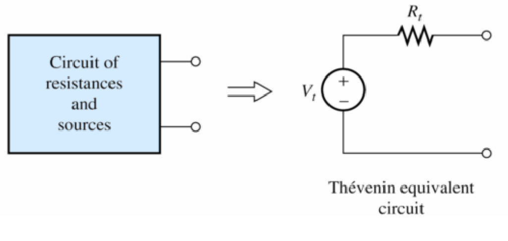
Alright, first things first, what’s this Thevenin equivalent principle? Well, the Thevenin theorem is a super handy tool in circuit analysis that allows us to replace a complex linear circuit with just a single voltage source and a series resistor. This equivalent circuit helps us understand and analyze complex circuits more easily. Pretty neat, right?
What is meant by Thevenin’s equivalent voltage (Vth)?
Now, let’s talk about finding the Thevenin equivalent voltage (Vth). Thevenin equivalent voltage is the open-circuit voltage across the load terminals. One way to calculate Vth is by using the voltage division. You know how a voltage divider splits the total voltage across multiple resistors? Well, we can use that principle to find the Thevenin equivalent voltage. Here’s how it goes:
- Identify the circuit you want to analyze.
- Find the total resistance of the circuit by combining all the resistors.
- Determine the voltage across the load resistor (the one you’re interested in).
- Use the voltage divider formula (Voc = Vin * Rload / Rtotal) to calculate the Thevenin equivalent voltage.
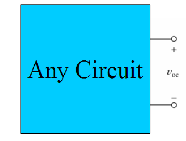
Is the Thévenin voltage the open circuit voltage? (Voc )
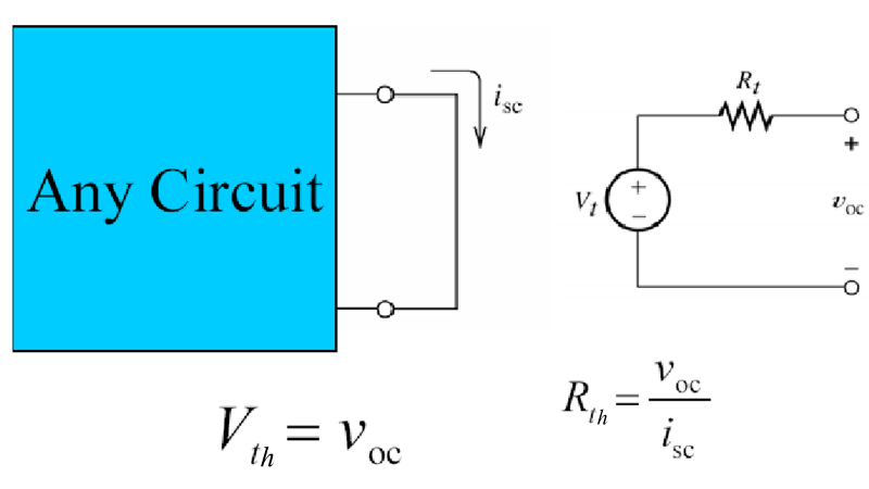
Well, it’s pretty straightforward Voc = Vth thevenin voltage is the open circuit voltage. When We disconnect everything connected to the circuit and measure the voltage across the points where the load was connected. By doing this, we can determine the Thevenin equivalent resistance.
What is Thevenin’s equivalent resistance (Rth)?
Thevenin’s equivalent resistance (Rth) is another essential component of the Thevenin equivalent circuit, Rth is the equivalent resistance across the load terminals after removing all the independent sources. It helps us understand how the original circuit behaves from the perspective of external devices connected to it. Here’s how we can find the Thevenin equivalent resistance using the open-circuit voltage method:
- Identify the circuit you want to analyze.
- Disconnect all the loads and voltage sources.
- Measure the open-circuit voltage (Voc) across the points where the load was connected.
- Reconnect the load and calculate the equivalent resistance (Rth) using Ohm’s Law (Rth = Voc / Ioc), where Ioc is the current flowing when the circuit is open.
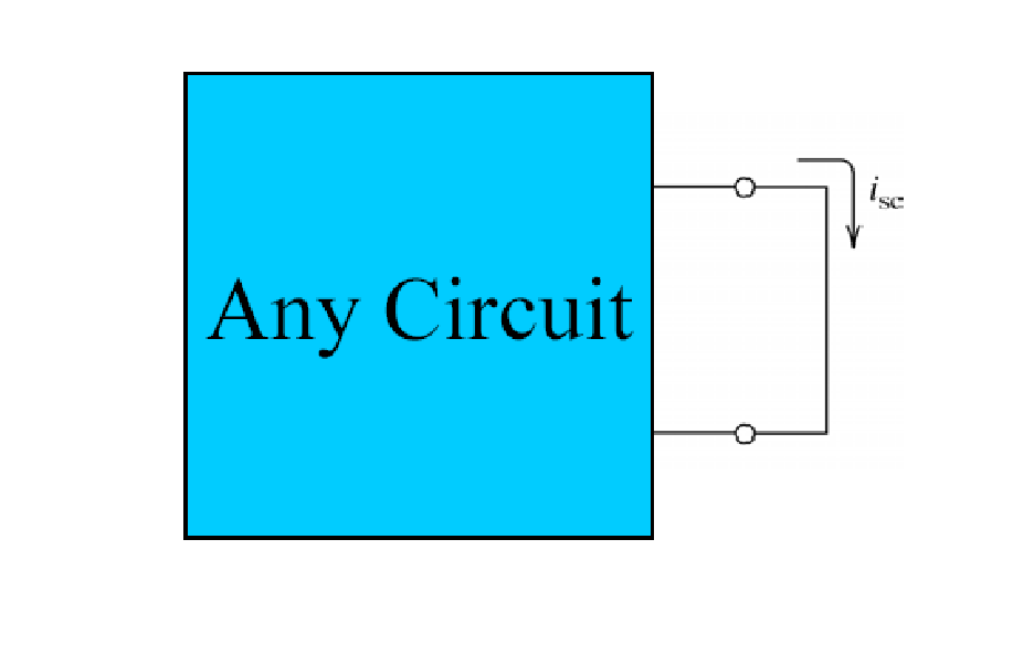
What is a short circuit?
Electricity will always take the path of least resistance, as a result a short circuit is when an electrical current takes a shortcut and bypasses part of the circuit. This can happen when two wires touch each other, or when there is a break in the circuit. A short circuit can cause a lot of problems, like overheating, sparks, fires, or even explosions. That’s why you should always be careful when handling electrical devices and wires.
What is short circuit in Thevenin Theorem?
Okay, so now let’s talk about another method to find the Thevenin equivalent circuit: the short-circuit current method. Here’s how it works:
- Identify the circuit you want to analyze.
- Short-circuit the points where the load was connected.
- Measure the short-circuit current (Isc) flowing through the short circuit.
- Calculate the Thevenin equivalent resistance using Ohm’s Law (Rth = Voc / Isc), where Voc is the voltage across the load when the circuit is open.
In a nutshell, the short-circuit current method involves creating a short circuit at the load points and measuring the current. This method helps us determine the Rth.
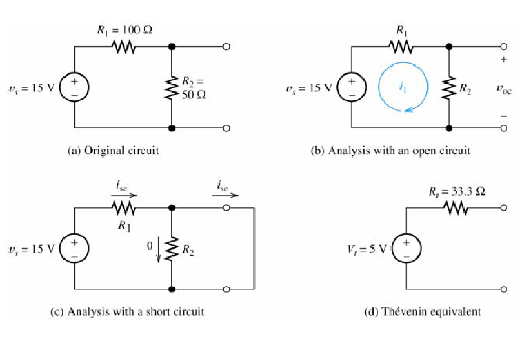
How do you find Thevenin equivalent steps?
- Identify your pair of nodes.
- Measure the open circuit voltage (Find Voc)
- Analysis with a short circuit (Find Rth & Isc)
- Create Thevenin equivalent circuit. The Thevenin equivalent consists of a voltage source Vth
in series with Rth
Its important to remember when zeroing a voltage source, it becomes a short circuit. When zeroing a current source, it becomes an open circuit. We can find the Thevenin resistance by zeroing the sources in the original network and then computing the resistance between the terminals.
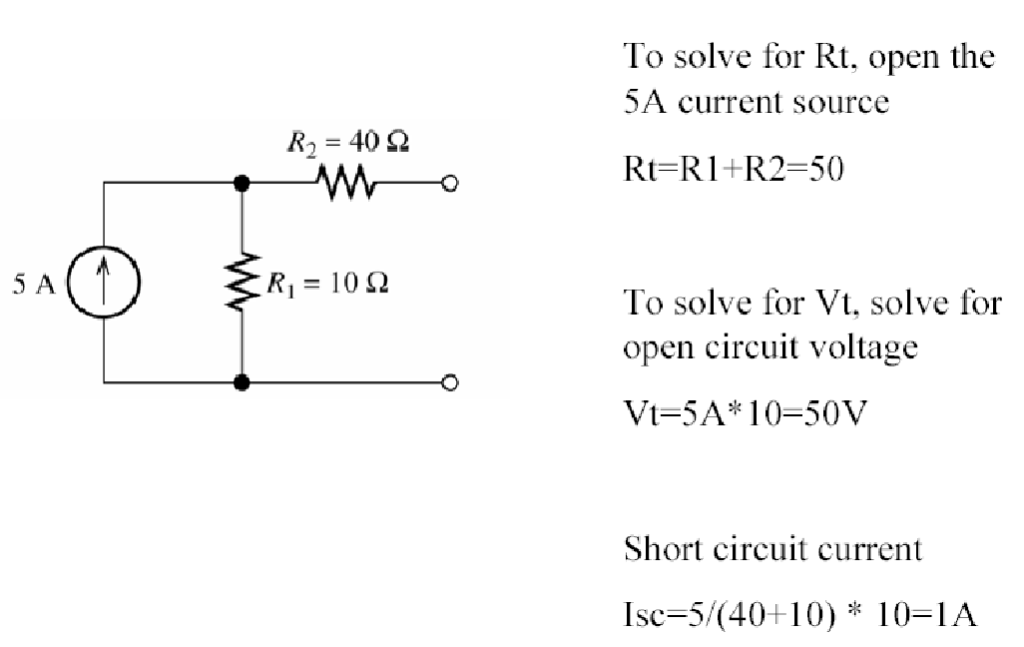
Sample Problem with steps
Sample Lab Report
Abstract:
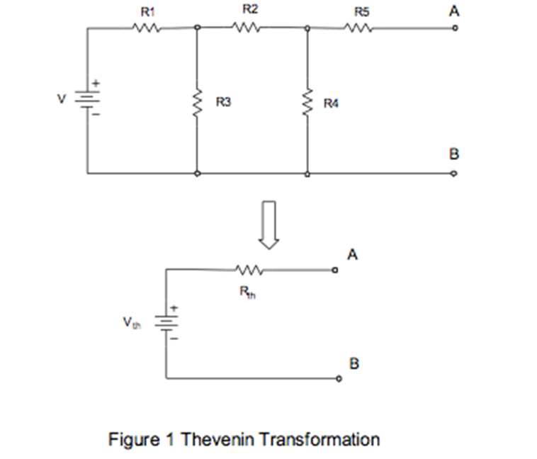
Using a breadboard and 5 resistors a circuit was constructed as shown below, this circuit was then connected to a 10V-voltage power supply, and using a multi-meter connected to points A and B, voltage and current measurements were taken. See Figure 1 Thevenin transformation below. Using the principle of source transformation an equivalent Thevenin circuit was constructed and using a multi-meter connected to points A and B of the Thevenin circuit, voltage, and current measurements were also taken. This confirmed that the original circuit could be replaced with a simplified equivalent circuit with just one voltage source and one resistor. These values were then compared to the algebraic results, which were computed as the principal of circuit transformation.
Objective:
The purpose of this laboratory exercise was to confirm that by using the Thevenin circuit transformation principle you can simplify any circuit, within the range of voltage and current used in this experiment.
Theory:
According to the principle of Thevenin’s Equivalent Circuit (TEC) the complicated circuit can be replaced with a simplified equivalent circuit with just one voltage source and one resistor connected in series. You just need to calculate Rth and Vth and the simplified circuit will behave the same as the original.
Procedure:
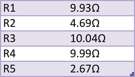
To bring to construct this equivalent circuit the first step is you have to find Thevenin’s equivalent resistance to the original circuit. Before you can do this you must first find the true resistance of each resistor by using a multimeter and measuring each resistor individually. See table 1: Resistance Measurements to see the full list of resistor values.
Once you have the actual resistance values for each resistor in the circuit then you must replace the voltage source with a short wire and just simply the circuit using the principals of equivalent resistance.
(1) Rth=(((R1//R3)+R2)//R4)+R5
R1//R3=4.99 Ω
4.99 Ω+R2=9.69 Ω
9.69//R4=4.92 Ω
4.92 Ω+R5=9.59 Ω= Rth
To find Isc, Kirchoff’s Current Law (KCL) was used. Suppose you name the junction located at the top left of the circuit in between R1, R2, and R3 as Node 1. If we assume I1 is entering node 1 while I2 and I3 are leaving node 1, the following KCL equation can be derived.
(2) KCLnode 1 = I1=I2+I3
If you name the junction located at the top right of the circuit in between R2, R4, and R5 as Node 2. If we assume I2 is entering node 2 while I4 is leaving node 2 and I3 has no current because it is open, then the following KCL equation can be derived.
(2) KCLnode 2 = I2=I4
Using equations (2) and (3) you can then apply Ohms law which states that I=V/R to derive two simultaneous equations (4) and (5)
(4)
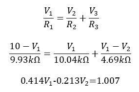
(5)
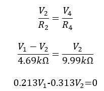
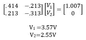
You can solve for V1 and V2 by plugging equations (4) and (5) into a matrix.
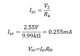
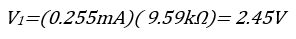
V2 is equal to the voltage at across AB assuming the bottom node of the circuit is ground. Then using Ohms’s law you can find Isc. Once you have Isc just apply Ohms law once again to find Voc.
(6)
Data and Analysis:
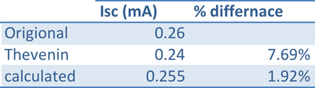
The results from this experiment do confirm you can simply circuit by using the principles of TEC. When comparing the Thevenin and calculated results to the original circuit you see that all the calculated and Thevenin Isc currents were within 7.69% of the original value. This is a low % difference, which just reinforces the validity of the results and TEC. To see a full list of all calculated Isc currents see Table 2 measured vs calculated Isc below.
When comparing the Thevenin and calculated Voc voltages to the originally measured voltage the results show that the calculated and Thevenin voltages are within 3.54% of the original voltage. This is an low % difference, which proves that there is a very good correlation between these three values and reinforces the validity of the results. To see the full list of Voc voltages see Table 3 measured vs calculated Voc below.
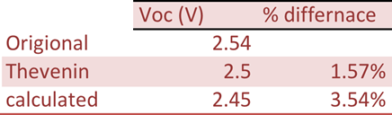
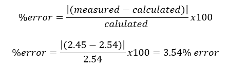
Conclusions: Table 2 of the previous section shows that the measured and calculated values of the Isc current, agree to within 7.69%. Table 3 shows that the measured and calculated values of Voc voltages agree within 3.54%. see equation (7) below to see the sample calculation of % error
(7)
After performing this experiment it can be concluded that TEC is a valid method for analyzing and simplifying an electrical circuit.
Appendix
Equipment: Tektronix PS 280 DC Power Supply, Tektronix CDM 250 Digital Multimeter, 5 resistors with resistance values between 1kΩ-10kΩ, and a breadboard.