Voltage and Current Division
Introduction
Hey there, folks! Today, we’re going to embark on a journey to master the art of voltage and current division. It might sound intimidating at first, but fear not! Voltage and current dividers are simple concepts that are easy to grasp and apply. They may seem so straightforward that one might question the need to learn them as distinct techniques. However, when combined with the concept of equivalent resistances, divider methods become one of the most commonly used techniques in electronics.
Understanding how to use dividers enables us to quickly interpret circuit behavior, identify crucial voltages and currents, and analyze circuits efficiently. While an engineer could technically analyze and design circuits without including voltage and current dividers in their toolkit, doing so would result in a waste of time, as they would need to write unnecessary Kirchhoff’s Voltage Law (KVL) and Kirchhoff’s Current Law (KCL) equations. I’m here to guide you through the ins and outs of this essential aspect of electrical circuits. So, let’s buckle up and get ready to conquer voltage and current like a boss!
Understanding Voltage and Current Division Basics
Before we dive into the nitty-gritty details, let’s make sure we’re all on the same page. Electric circuits can be categorized into two main types: series circuits and parallel circuits, depending on how the components are arranged.
In a series circuit, the components are connected in a chain, while in a parallel circuit, all components are connected between two common points. Series circuits function as voltage divider circuits, whereas parallel circuits function as current divider circuits. So, what exactly are voltage and current division?
What is voltage and current division?
Voltage /current division are useful technique used to express the voltage and current across one of the several series or parallel resistors in a circuit in terms of the voltage and current.
- voltage division refers to the process of splitting a voltage into smaller parts across different components in a circuit.
- current division involves distributing the current flowing through a circuit among multiple paths.
To achieve voltage and current division, we have two trusty circuits in our toolkit: the voltage divider and the current divider. These circuits help us tame the flow of voltage and current, allowing us to control and manipulate a circuit.
Voltage Division: Balancing the Voltage Game
Alright, let’s focus our attention on voltage division. Imagine you have a voltage source, and you want to divide it between different components in your circuit. This is where the voltage divider circuit comes into play.
What is an example of a voltage divider circuit?
The best example for a voltage divider is by connecting two or more resistors in series.

Where is the voltage divider formula used?
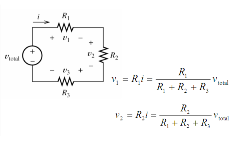
The heart of the voltage divider circuit is the voltage divider equation, which states that the output voltage (Vout) across a particular component is proportional to its resistance (R) compared to the total resistance in the circuit. In simple terms, the higher the resistance, the larger the voltage drop across that component. See the sample circuit and equations below:
Example
Calculating the output voltage in a voltage divider circuit is a piece of cake. You just need to know the values of the resistors involved and apply the voltage divider equation. Let’s say you have a 12-volt source and two resistors in series, one with a value of 2000 ohms and the other with a value of 1000 ohms. Using the voltage divider equation, you can determine the voltage drop across each resistor and calculate the output voltage
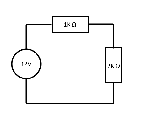
Solution:
Vout = Vin * (R2 / (R1 + R2))
In our case, plugging in the values:
Vout = 12V * (1kΩ / (2kΩ + 1kΩ))
= 12V * (1kΩ / 3kΩ)
≈ 4V
Now, let’s talk about some practical tips to ensure effective voltage division. First, make sure the resistors you choose have appropriate values that suit your desired voltage splits. If the resistance values are too small, the voltage drops might be negligible, while large resistance values can cause excessive voltage drops. It’s all about finding the right balance.
Additionally, consider the power ratings of the resistors. Higher power ratings are necessary if the voltage across the resistors is substantial to avoid overheating and potential damage.
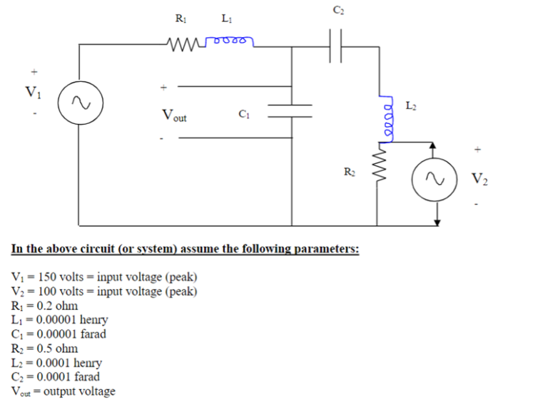
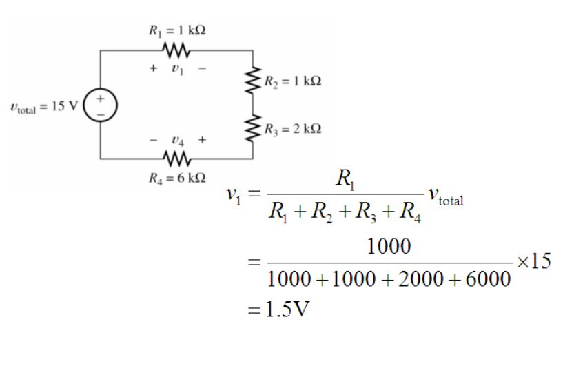
Sample Problem
Current Division: Sharing the Current Load
Moving on to the current division, imagine you have a current flowing through a circuit, and you want to divide it between different branches. Enter the current divider circuit, our trusty sidekick in this endeavor.
When can you use the current division?
Current division can be used anytime two or more resistors are connected in parallel.
What is the principle of current division?
Anytime you have a parallel circuit the amount of current that flows through the branch gets “divided” amongst each branch. This is the foundation for the current division and the current divider equation.
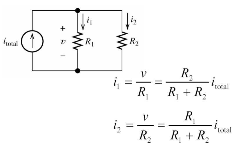
Similar to voltage division, current division involves the use of a simple equation, known as the current divider equation. According to this equation, the output current (Iout) in a specific branch is inversely proportional to its resistance (R) compared to the total resistance in the circuit. In simpler terms, the higher the resistance, the smaller the current flowing through that branch.
Example
Calculating the output current in a current divider circuit is a breeze. Let’s say you have a current source of 2 amperes and two resistors in parallel, one with a value of 1000 ohms and the other with a value of 2000 ohms. Using the current divider equation, you can determine the current flowing through each branch and calculate the output current.
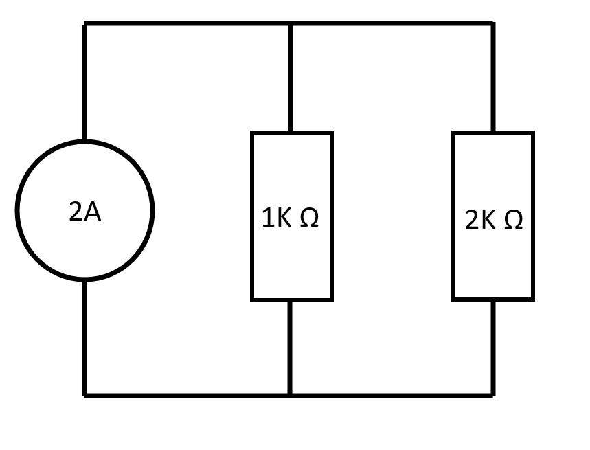
Solution:
Iout = Iin * (Rtotal / R)
In our case, plugging in the values:
Iout = 2A * (3kΩ / (1kΩ + 2kΩ))
= 2A * (3kΩ / 3kΩ)
≈ 2A
So, in this example, the output current in each branch would be approximately 2 amperes.
Remember, when working with the current division, ensure that the sum of the currents in the branches matches the total current flowing into the circuit. It’s all about preserving the flow of current and ensuring that it is distributed efficiently.
Sample Problem
Advanced Techniques for Voltage and Current Division
Now that we have a solid grasp of the basics, let’s level up our voltage and current division game with some advanced techniques.
One important consideration when working with voltage and current dividers is the tolerance of the components involved. Resistors, for instance, have a specified tolerance that indicates the acceptable variation in their resistance value. To mitigate the impact of component tolerances, you can use precision resistors or select resistors with tolerances that won’t significantly affect your voltage or current division calculations.
Another fascinating aspect to explore is feedback in voltage and current divider circuits. Feedback allows you to stabilize and control the output voltage or current by using the output itself as an input. This can be achieved through various feedback mechanisms like op-amps or transistor configurations, enabling precise voltage and current regulation in your circuits.
Lastly, it’s worth mentioning that voltage and current dividers find application in numerous real-world scenarios. From sensor circuits and voltage regulation to audio amplifiers and power supplies, these concepts are fundamental building blocks in the world
of electronics. Understanding voltage and current division opens up a whole new realm of possibilities in designing and optimizing circuits for various applications.
Conclusion
And there you have it, my friends! We’ve journeyed through the realm of voltage and current division, unraveling its mysteries along the way. We’ve learned how to divide and conquer voltage and current like seasoned electrical wizards.
Remember, voltage division allows us to split voltage across components, while current division enables us to distribute current among different paths. By harnessing the power of voltage and current dividers, we gain control over electrical quantities, making circuit design more efficient and tailored to our specific needs.
As you continue your exploration of electronics, don’t forget to consider advanced techniques such as component tolerance management and feedback mechanisms. These tricks will take your voltage and current division skills to the next level, ensuring precise and reliable circuit performance.
So, go forth, my fellow enthusiasts, and apply your newfound knowledge. Master the art of voltage and current division, and let your circuits shine with efficiency and elegance. The world of electronics awaits your innovative creations!