What You Need to Know About Maximum Power Transfer and Why It Matters
Introduction
Today, I want to talk to you about something that might sound a bit technical at first, but trust me, it’s important and can be pretty interesting. We’re going to dive into the world of maximum power transfer and why it actually matters. So, let’s get started!
What is the concept of power transfer?
Okay, before we delve into the nitty-gritty of maximum power transfer, we need to grasp the concept of power itself. Simply put, power is defined formally as units of energy per unit time. It’s what keeps our electrical devices running and our world moving. So power transfer or transmission is the movement of energy from its origin to a location where it is useful.

Now, when it comes to electrical circuits the power source is either a voltage or current source and that electricity travels to any type of load such as a laptop, phone , or even just a light bulb. Picture this: you have a circuit where electricity needs to flow from the 12V electrical outlet to your celling fan. But how do you achieve that?
What is maximum power transfer theorem in simple words?
Well, my friends, this is where the maximum power transfer theorem comes into play. This theorem states that the maximum power is transferred from a source to a load when the impedance of the load matches the impedance of the source. In simpler terms, it means that to generate maximum power transfer the resistance of the load must be equal to the resistance of the available source.
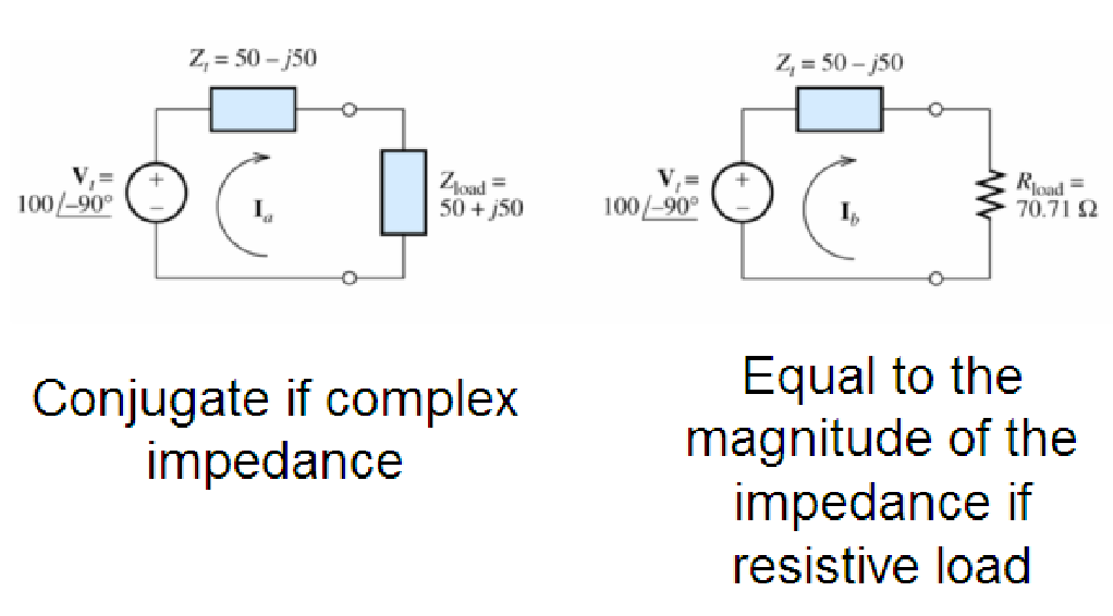
- If the load can take on any complex value, maximum power transfer is attained for a load impedance equal to the complex conjugate of the Thevenin impedance.
- If the load is required to be a pure resistance, maximum power transfer is attained for a load resistance equal to the magnitude of the Thevenin impedance.
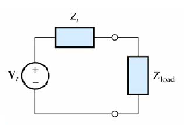
Remember that the load resistance that absorbs the maximum power from a two-terminal circuit is equal to the Thevenin resistance.

Example
What is the rule of impedance matching?
I know, impedance sounds like a complex term, but it’s not as daunting as it seems. Think of impedance as a measure of how much an electrical circuit resists the flow of current. In electrical devices, impedance matching is a common practice of adjusting the input or output impedance to a desired value to maximize power transfer or minimize signal reflection.
Why is impedance matching so important, you ask? Well, imagine a situation where the load impedance is too high compared to the source impedance. In this case, only a small portion of the power will be transferred, leaving most of it wasted. On the other hand, if the load impedance is too low, the power transfer will be inefficient, leading to potential overheating and damage of electronics.
What is the real life application of Maximum power transfer?
Now that we have a good grasp of the concept, let’s talk about some practical applications where maximum power transfer plays a vital role. One prime example is audio systems, like speakers. Matching the speaker impedance with the amplifier’s output impedance ensures that the speakers receive the maximum power and produce high-quality sound.

Another relevant example is wireless charging. Many of us rely on wireless charging pads for our smartphones or other devices. Did you know that these chargers are designed to optimize power transfer efficiency? By carefully aligning the receiver’s and transmitter’s impedance, they ensure that power is transferred effectively.
Sample Lab Report
Abstract
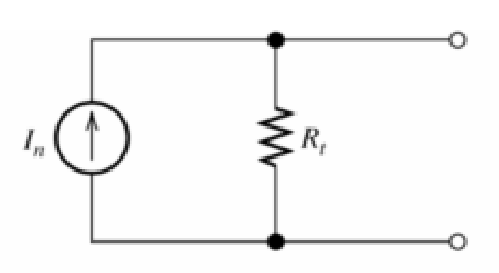
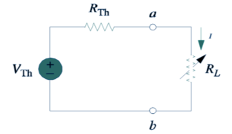
Using a breadboard and several different resistors which would represent the variable loaded resistor (RL) several Thevenin circuits were constructed see figure 1 below. These circuits were then connected to a 10V-voltage power supply (Vth) and used a multi-meter voltage and current measurements were taken for each circuit. After calculating the power for each resistor value, the measurements were compared. And it was after careful analysis it was then determined which resistor would maximize the power transfer from a DC voltage source to a resistive load of nominal resistor values of 3.3kΩ (Rth).
Objective: The purpose of this laboratory exercise was to determine the load resistance RL that will maximize the power transferred from a DC voltage source to a resistive load.
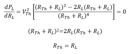
Theory: According to the principle of Thevenin’s Equivalent Circuit (TEC) you can maximize the power transfer of a DC circuit by having Rth = RL. Please see the proof below.
To be able to determine the value of RL which will maximize PL, set dPL/dRL = 0
Procedure
Before you can construct Thevenin’s equivalent circuit first grab 8 different resistors and measure the actual resistance values for each resistor using the multimeter. Make sure to grab 4 resistors, which has a resistance value over 3.3kΩ, and 4 that have a resistance value below 3.3kΩ. Once you have the actual resistance values for each resistor in the circuit then you must construct a Thevenin’s circuit and take voltage and current measurements for each resistor. See Table 1 below.

Once you have Power and voltage measurements for all resistors you must calculate the power dissipated by the resistor.
(1) P = IV
P=(1.93mA)(3.66V)=7.06mW
After you have calculated the power for each of your resistors plot the data for Resistor vs Power and graphically determine the resistor value to maximize the power transfer. Find the trend line which best represents your data, and find the maximum of your function. See figure 2 at the top of the next page.
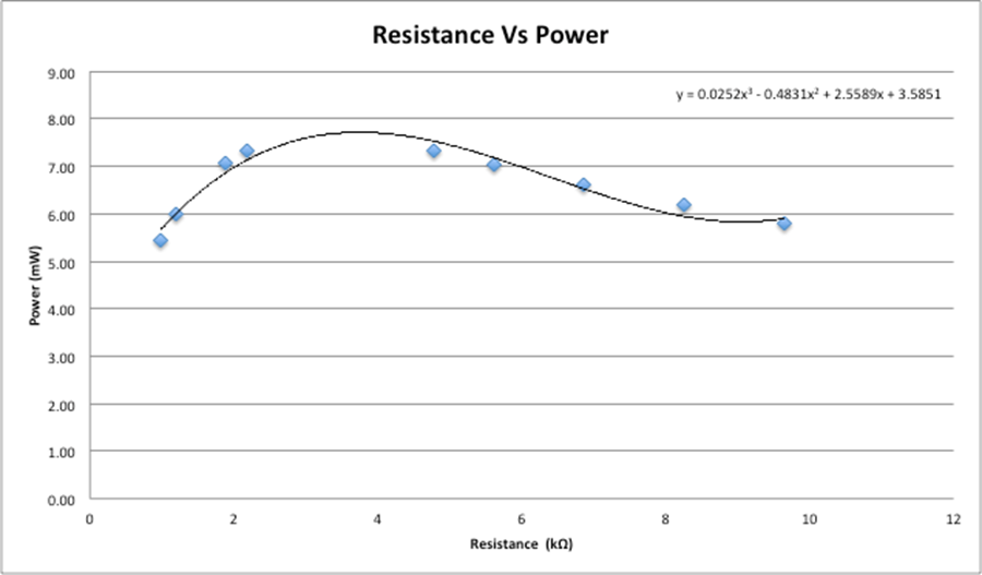
Based on the trend line we can estimate that the resistance value which would give you the maximum power transfer would be around 3.75-4.0kΩ
Data and Analysis
To compare the theoretical resistances to the nominal resistance first take the midpoint of the estimated resistance (3.875kΩ) and using the percent difference formula you are able to find a percent difference of 17.4%.
(2)

This % difference was higher than desired. Some of the factors that might have caused this was the number of data points that were collected; with more data, you would be able to more adequately represent the data points. Also, there are much better ways to find the theoretical resistance than just eyeballing the graph.
Appendix
Equipment: Tektronix PS 280 DC Power Supply, Tektronix CDM 250 Digital Multimeter, 5 resistors with resistance values between 1kΩ-10kΩ, and a breadboard.