Planetary Gear: Explained
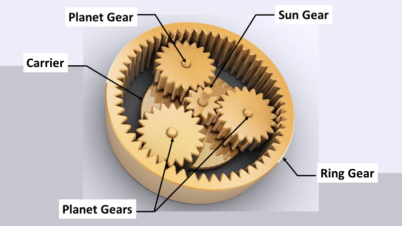
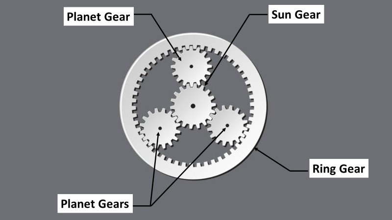
A planetary gear system also known as an Epicyclic gearing or planetary gearing. It consists of spur gears arranged in an epicyclic configuration. In this setup, a central gear, known as the sun gear, acts as the input and drives the system. Multiple “driven” gears, or planets, orbiting the sun gear within a gearbox. These planets mesh with an internal ring gear, forming an internal spur gear design.
Planetary gear systems find extensive use in a range of mechanical transmissions. For example they can be found in helicopters, wind turbines, vehicles, and mining machinery. This popularity stems from their compactness, high transmission efficiency, and ability to achieve large transmission ratios.
History of The Planetary Gear
Around 500 BCE, the Greeks introduced the concept of epicycles. Which are circles moving along larger circular paths. This theory would later be used by Claudius Ptolemy in 148 CE in the Almagest to approximate planetary movements observed in the sky. The Antikythera Mechanism, dating back to around 80 BCE, featured gearing that closely mimicked the moon’s elliptical path and even accounted for its nine-year precession. This was despite the Greeks interpreting the motion as epicyclic rather than elliptical.
In the 2nd century AD, Ptolemy utilized rotating deferents and epicycles in epicyclic gear trains described in The Mathematical Syntaxis, or Almagest, to predict planetary motions. This method assumed that the Sun, Moon, and the five known planets followed paths traced by a point on the planet gear, forming a curve known as an epitrochoid. Epicyclic gearing continued to be used in various applications, including Richard of Wallingford’s astronomical clock in the 14th century and Agostino Ramelli’s book wheel in 1588, which contained epicyclic gearing to maintain the books’ orientation.
What is the importance of a Planetary Gearset in Automatic Transmissions?
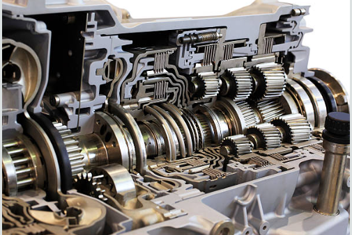
The importance of a planetary gearset in automatic transmissions lies in its ability to create all the gear ratios required for smooth and efficient gear changes. Planetary gear trains (PGTs), known for their compact structure, wide transmission range, and high efficiency, are typically the core structure of AT mechanisms.
A planetary gearset allows automatic transmissions to seamlessly adjust to different speeds. This results in a more comfortable and effortless driving experience. The configuration of an automatic transmission directly impacts the vehicle’s performance and driving dynamics. Thus making the design of high-performance automatic transmissions a complex and challenging task. A comprehensive understanding and innovative design of PGTs are essential for developing cutting-edge automatic transmission systems.
Many companies have developed advanced automatic transmissions with multiple gears, such as ZF’s 5-speed, 6-speed, 8-speed, and 9-speed ATs. Another example would be Toyota’s 5-speed, 6-speed, 8-speed, and 10-speed ATs, Allison’s 6-speed and 7-speed ATs, and Jatco’s 7-speed AT. Despite these advancements, there remains potential for designing new AT mechanisms that offer superior kinematic and dynamic performance, high transmission efficiency, smooth shifting, and ease of manufacturing.
Single planetary gear set vs double planetary gears set
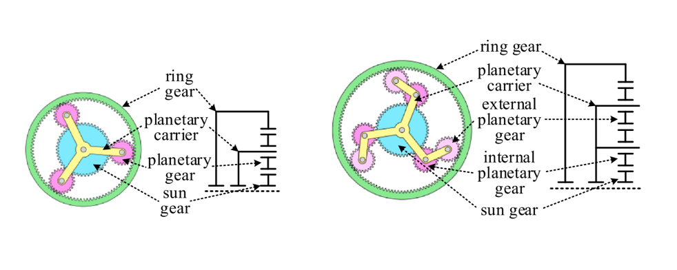
The mechanism used in an automatic transmission (AT) is a planetary gear mechanism. Its core structure is a multiple-row planetary gear train (PGT) formed by combining multiple basic planetary gear sets (PGSs). There are two forms of basic PGSs: the single-planetary-gear PGS and the double-planetary-gears PGS, as shown below.
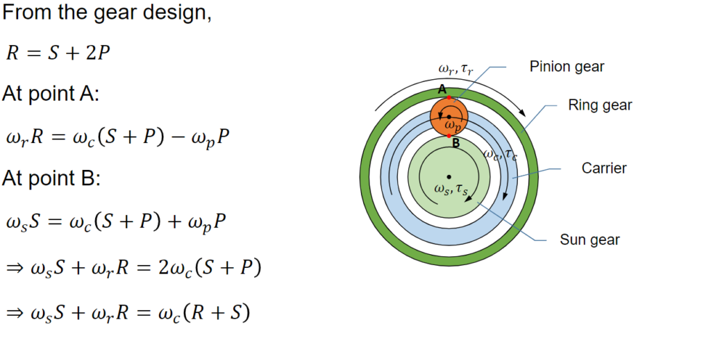
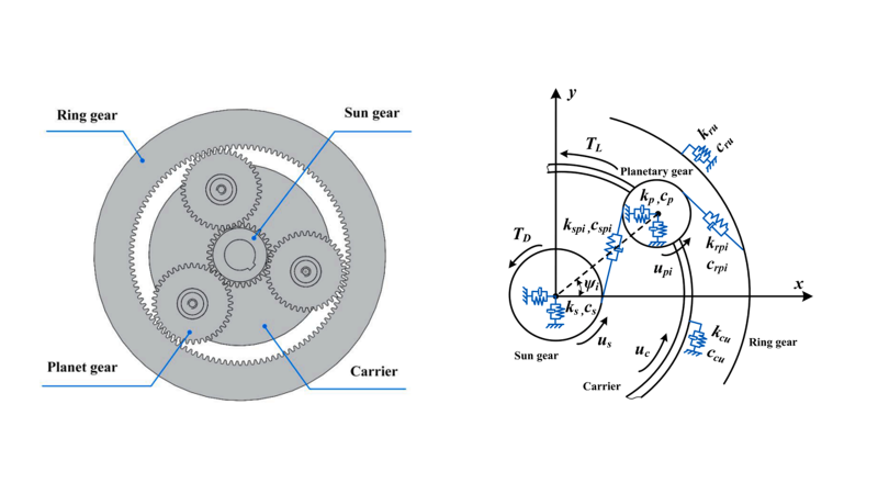
Kinematics of a Planetary Gear Set
The kinematics of a planetary gear set are defined by the relationships between the rotational speeds of its components. The main componets include
- Sun gear (S)
- Ring gear (R),
- and pinion gear (P), also known as the planetary gear.
Sample Problem 1
The following information about a power-split HEV using one PSD is given:
- The sun gear/ring gear radius is 3.0/7.0
- The engine speed is fixed at 2000 rpm.
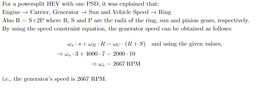
Calculate the generator speed when the vehicle is driving at 100 mph. Assume that the ring gear speed is
4000 rpm at this vehicle speed.
Sample Problem 1: Solution
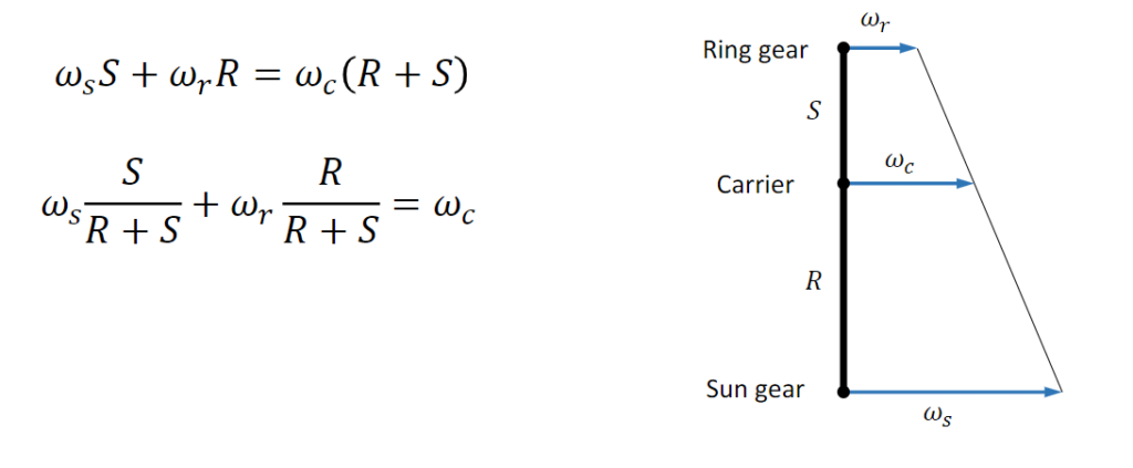
Lever Analogy: Speed
The lever analogy is a method used to analyze the kinematics of a planetary gear set by comparing it to a system of interconnected levers. In this analogy, the sun gear, planet carrier, and ring gear are represented as three nodes connected by levers. The motion of these nodes is constrained by the speed constraint, which dictates that the sum of the linear speeds of the nodes must be zero due to the rigid body nature of the system. This constraint reduces the system to two degrees of freedom (2 DOF), simplifying the analysis of the gear set’s kinematics.
Torque Analysis of a Planetary Gear Set
The torque analysis of a planetary gear set involves determining the dynamics of the gear nodes, which can be achieved by examining the free-body diagram of the system. This diagram illustrates the forces acting on each component of the gear set, including the sun gear, planet gears, and ring gear, as well as the carrier. By applying the principles of static equilibrium and Newton’s laws of motion to the free body diagram, the torques acting on each gear can be calculated. This analysis is crucial for understanding how torque is transmitted through the gear set and how it affects the motion of the gears.
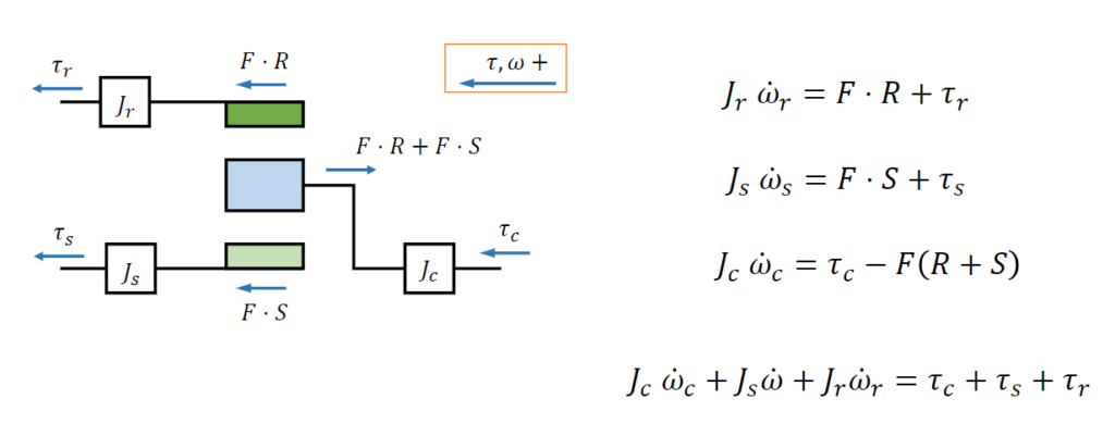
Static Torque Analysis
Static torque analysis of a planetary gear set involves examining the torque distribution among its components under static conditions. The analysis is based on several assumptions, including negligible gear inertia (zero inertia) and the conservation of power, meaning there is no friction loss. Additionally, it is assumed that the torque input to the carrier is divided by a fixed ratio between the ring and sun gears.
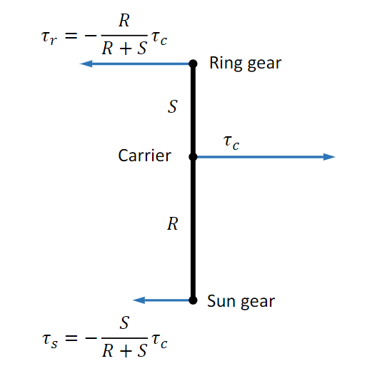
These assumptions allow for simplification of the analysis, leading to equations such as 𝜏𝑠 + 𝜏𝑟 + 𝜏𝑐 = 0, which states that the sum of the torques acting on the sun gear, ring gear, and carrier is zero. Similarly, the equation 𝜔𝑠𝜏𝑠 + 𝜔𝑟𝜏𝑟 + 𝜔𝑐𝜏𝑐 = 0 represents the conservation of power in the system. Static torque analysis provides insights into the torque distribution within the gear set and is essential for understanding its mechanical behavior.
Sample Problem 2
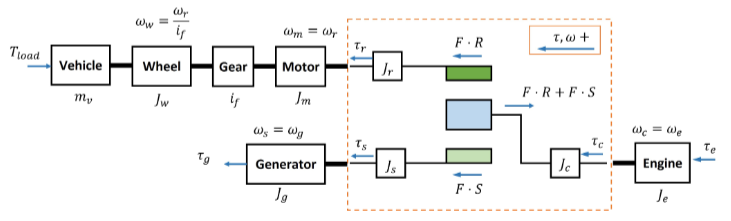
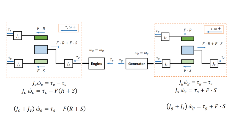
For this powertrain system, derive the governing equations. Here, vehicle mass is mv, vehicle speed is v,
wheel radius is rw, final drive torque ratio is if (torque is amplified by a factor of if ), and the vehicle load
(aerodynamic plus rolling resistance) is Tload. The engine, motor, and generator torque terms are denoted asτe, τm, and τg, respectively. The engine, motor, and generator inertia terms are denoted as Je, Jm, and Jg , respectively. Ignore the gearbox inertia.
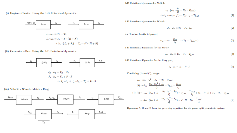
Sample Problem 2 – Solution
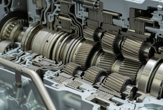
Industries and Applications Utilizing Planetary Gearing
Planetary gear systems find application in a broad array of industries, including conventional automotive and off-road transmissions, wheel drive motors, industrial conveying systems, and more. Surprisingly, even a seemingly straightforward application like a bicycle employs planetary gearing for its shifting mechanism. Additionally, these gears can serve as powertrains connecting internal combustion engines or electric motors such as in a power split devices in a power-split HEV.
Example of a Planetary Gear Set in industry
An example of a planetary gear set in industry is the Toyota Hybrid System (THS-II) used in Toyota hybrid vehicles. In this system, the sun gear is connected to the generator, the carrier is linked to the engine, and the ring gear is attached to the motor.
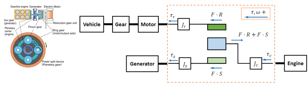
This configuration allows for a variety of operational modes, including electric-only driving, engine-only driving, and a combination of both, known as hybrid operation. By using the planetary gear set in this way, Toyota can optimize the power flow between the engine, generator, and motor, maximizing efficiency and performance in their hybrid vehicles.
Basic Toyota Hybrid System (THS-II) Operations
The Basic Toyota Hybrid System (THS-II) operates through three key stages. Firstly, at rest, the system is in standby mode, with the engine off and the motor serving as the sole power source. During smooth launch, the motor is the sole power source, providing the necessary torque for the vehicle to move forward smoothly. In this stage, the engine remains off, contributing to reduced fuel consumption and emissions.
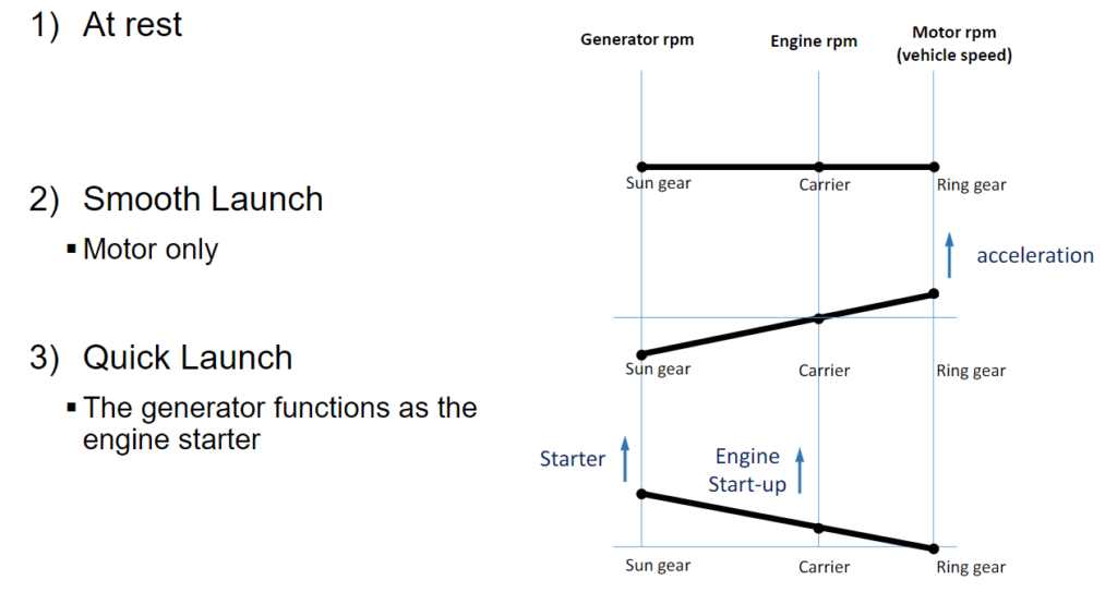
Lastly, during quick launch, the generator functions as the engine starter, assisting the motor in providing additional torque for acceleration. This stage allows for quick and efficient acceleration, with the engine seamlessly transitioning to providing power once the vehicle is in motion. The THS-II system optimizes the use of the electric motor and engine to enhance fuel efficiency and performance in Toyota hybrid vehicles.
Power splitting
Power splitting refers to a system where multiple components can act as outputs. For instance, in a setup where the input is linked to the ring gear, the sun gear connects to one output, and the planet carrier connects to another output via a torque converter. Idler gears are positioned between the sun gear and the planets to ensure that the sun gear rotates in sync with the ring gear when the planet carrier is stationary. At low input speeds, the sun gear remains stationary due to the output load, causing the planet carrier to rotate in the same direction as the ring gear.

If the load is high enough, the torque converter’s turbine will not move, dissipating energy and causing the torque converter pump to slip. Increasing the input speed overcomes this load, allowing the converter turbine to drive the output shaft. Since the torque converter itself loads the planet carrier, both the planet carrier and the sun gear draw energy from the system and transfer it to the output shaft.
Planet Balancing
Planet gears in a gear system are often not perfectly balanced, leading to potential issues. For example the planet being closer/ further from the sun axis, or slight misalignment of the carrier rotation axis. This imbalance becomes more likely as manufacturing precision decreases and the number of planets increases.
In some cases, the gear system can tolerate these imbalances, and the planets may eventually adjust to distribute the load more evenly through wear. However, certain designs are sensitive to even minor imbalances and may require high-precision components and assemblies to compensate. One approach to mitigate imbalances is to precisely determine balanced locations for the planet gears around the sun gear’s axis.
Other methods to balance the planet loads include using floating subassemblies or flexible mounts that allow small radial movements of the sun or planet carrier. This flexibility allows components to continually adjust, helping to even out uneven loading. While soft mounting assembly parts is common, stiff assemblies can offer advantages over flexible ones, making the choice between them less straightforward.
Defects in Planetary Gear Sets
Incorrect installation, material defects, machining errors, overloading, and other factors can lead to gear faults such as tooth cracking, pitting, wear, and breakage. These faults can result in excessive vibrations and noise in planetary gear systems, and in severe cases, lead to machine failures and catastrophic accidents. To ensure the reliable operation of planetary gear systems, it is crucial to accurately monitor their health and provide early warnings before major failures occur.
Effective Method for Detecting Gear Faults
Vibration analysis is considered an effective method for detecting gear faults. These faults, as they occur and progress, can decrease the load capacity of the gear tooth and alter dynamic parameters like time-varying mesh stiffness (TVMS) and transmission error, thereby affecting gear vibration characteristics. In a planetary gear system, which consists of multiple components (such as a sun gear, a ring gear, a carrier, and several planet gears) and complex vibration transmission paths, determining how gear faults evolve and impact vibration behaviors is challenging. Consequently, model-based simulation has emerged as a significant approach for gear fault detection and diagnosis.
There are three identified three key advantages of dynamic modeling: generating sufficient signals for training intelligent diagnosis algorithms, producing signals representing various fault conditions to develop and test diagnosis methods and features, and aiding in the understanding of complex vibration behaviors and fault characteristics. As a result, model-based diagnosis of planetary gear systems has garnered significant attention in recent years..
Conclusion
In conclusion, the planetary gear set is a versatile and efficient mechanism used in various industries and applications, from automotive transmissions to industrial machinery. Its design, with a sun gear, ring gear, and planet gears, allows for compactness, high transmission efficiency, and large transmission ratios. The kinematics of a planetary gear set can be analyzed using the lever analogy. Torque analysis involves examining the distribution of torques among its components. Static torque analysis is based on assumptions such as negligible gear inertia and power conservation.
An example of a planetary gear set in industry is the Toyota Hybrid System (THS-II). Here, the sun gear is connected to the generator, the carrier to the engine, and the ring gear to the motor. This setup enables various operational modes for efficient and smooth vehicle operation. Understanding the principles and operations of planetary gear sets is crucial for designing and optimizing gear systems in many applications.