Design of a scramjet engine
A scramjet, short for supersonic combustion ramjet, is an iteration of the ramjet airbreathing jet engine. Unlike traditional ramjets, scramjets ignite fuel in supersonic airflow. While both types rely on high vehicle speed to compress incoming air forcefully before combustion, a ramjet decelerates air to subsonic speeds using shock cones. In contrast, a scramjet lacks a shock cone and instead slows airflow with shockwaves from its ignition source. This design allows scramjets to efficiently operate at extremely high speeds.
While ramjet engines have seen use in a few operational military vehicles, scramjets have only been showcased in research test articles and experimental vehicles thus far.
What a scramjet is and how it works?
A scramjet is a type of rocket engine, which ignites an air-fuel mixture and then uses a nozzle to increase the flow velocity thus generating thrust. The main difference between a scramjet engine and another rocket-powered engine such as a ramjet engine is that the airflow in a scramjet remains supersonic throughout the entire engine. See Figure 1: Schematic of Scramjet below [1].

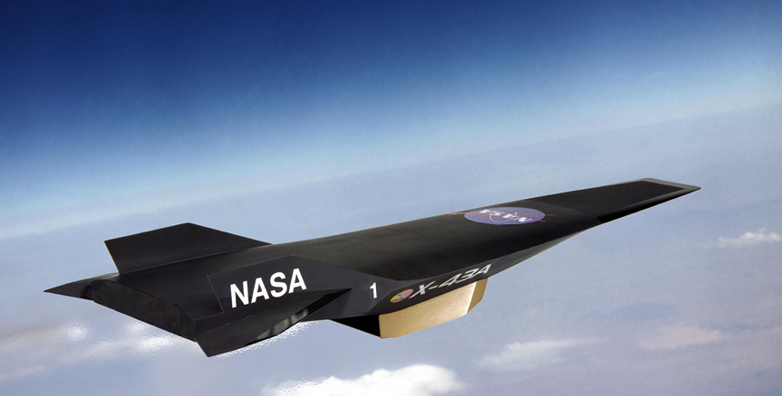
Researchers at NASA predict that a scramjet-powered aircraft could reach a top speed of Mach 15. A hypersonic flight at that speed would be able to reduce an 18-hour trip from Tokyo to New York to only 2 hours. Instead of carrying a large fuel tank, the scramjet would get the oxygen needed by the engine to combust from the atmosphere. As a result; the aircraft become smaller, lighter, and faster when compared to conventional jet engines powered aircraft. NASA’s Hyper-X program, which is responsible for the scramjet, in partnership with other companies is working on advancing this technology future. See Figure 2: Scramjet Powered Aircraft Prototype below [2].
The purpose of this project was to design a scramjet based on the idealized version shown below in figure 3: Scramjet Schematic. At state 1 the cross-sectional area of the inlet of the nozzle is 1 m2 and the air enters the scramjet at Mach 6. Fuel is burned in the combustion chamber between sections 2 and 3 resulting in the heat addition of 500 kJ/kg. The cross-sectional area in the combustion chamber is held at a constant 0.2 m2 thus compressing the incoming air. Finally, the airflow exits from station 4 at supersonic speeds. The cross-sectional area at the exit of the scramjet is the same as at the entrance. The air behaves isentropically between sections 1 to 2 as well as from 3 to 4.

Discussion
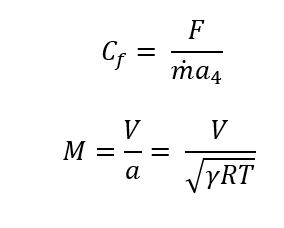
The first step to being able to design the scramjet propulsion system is first you have to calculate all the properties at each of the 4 sections of the scramjet. Using the definition of Mach number, which is the ratio of the velocity compared to the speed of sound, you are able to rearrange and solve for the velocity of the air as it enters the jet see equation 1.

(1)
Where V is the velocity of the air [m/s], M is the Mach number, g is the ratio of the specific heats of the gas also known as the adiabatic constant, R is the gas constant coefficient [J/kg-K] and T is the temperature of the air [K].
When you apply the law of conservation of mass, you get that the mass flow rate at each section must be equal as there is only one path for the flow to travel. So you can solve for the mass flow rate at section 1 and you know the mass flow rate throughout the whole jet see equation 2.

(2)
Where m_dot is mass flow rate [kg/s], ρ is the density of the air [kg/m3] the velocity of the air [m/s] When you are in the supersonic flow regime by reducing the cross-sectional area of the jet, the flow starts to slow down. Because it is assumed that between state 1 and state 2 the air behaves isentropically then both state 1 and state 2 are theoretically trying to reach the same critical area which would bring the flow down to Mach1 known as A*, Using this relationship is possible to solve for the Mach number at state 2. It is possible to solve for A* using Table A-1 from compressible flow tables [3], or using equation 3.
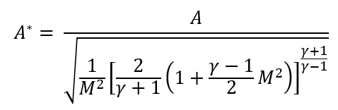
(3)
Once you have A* you can either use the tables or use the square of the ratio between A2 and A* to find the Mach number at state 2 using eq. 4.
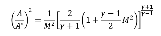
(4)
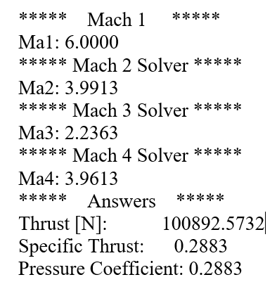
can then use that ratio to find A*, which is the critical area, this variable is constant across all 4 states. Then I divided A2/A* you can then use this ratio to determine Ma2. By knowing Ma2 you are able to solve for the rest of the properties in state 2, T0*, which is constant between state 2 and state 3. To get from state 2 to state 3 you use the heat addition equation q = Cp (T02- T03), all the variables in this equation are known other than T03. You can use the ratio between T03/T0* to evaluate Ma3. Used the tables to find (A3/A2*) evaluated at Ma3. A2* is the critical area from states 3 to 4. Use the ratio between A4/A2* to evaluate Ma4. By knowing the Mach number at every state you are able to find all the properties at each of the states. From that point, you just plug into your equations to solve for FThrust, Cf, and Cp


Sources
1) https://www.slideshare.net/virendragupta20/scramjet-engine
2) https://www.nasa.gov/missions/research/f_scramjets.html
3) Modern Compressible Flow: With Historical Perspective. John D. Anderson, JR 3rd Edition
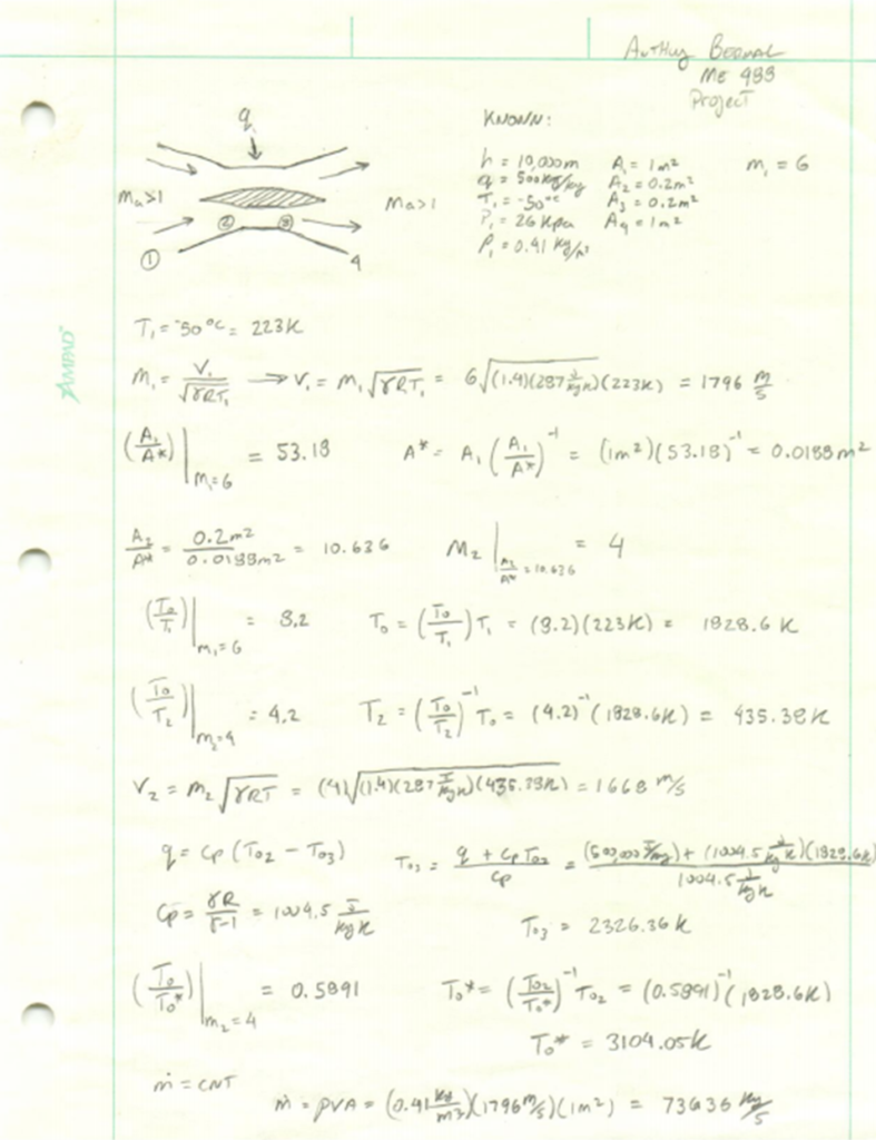
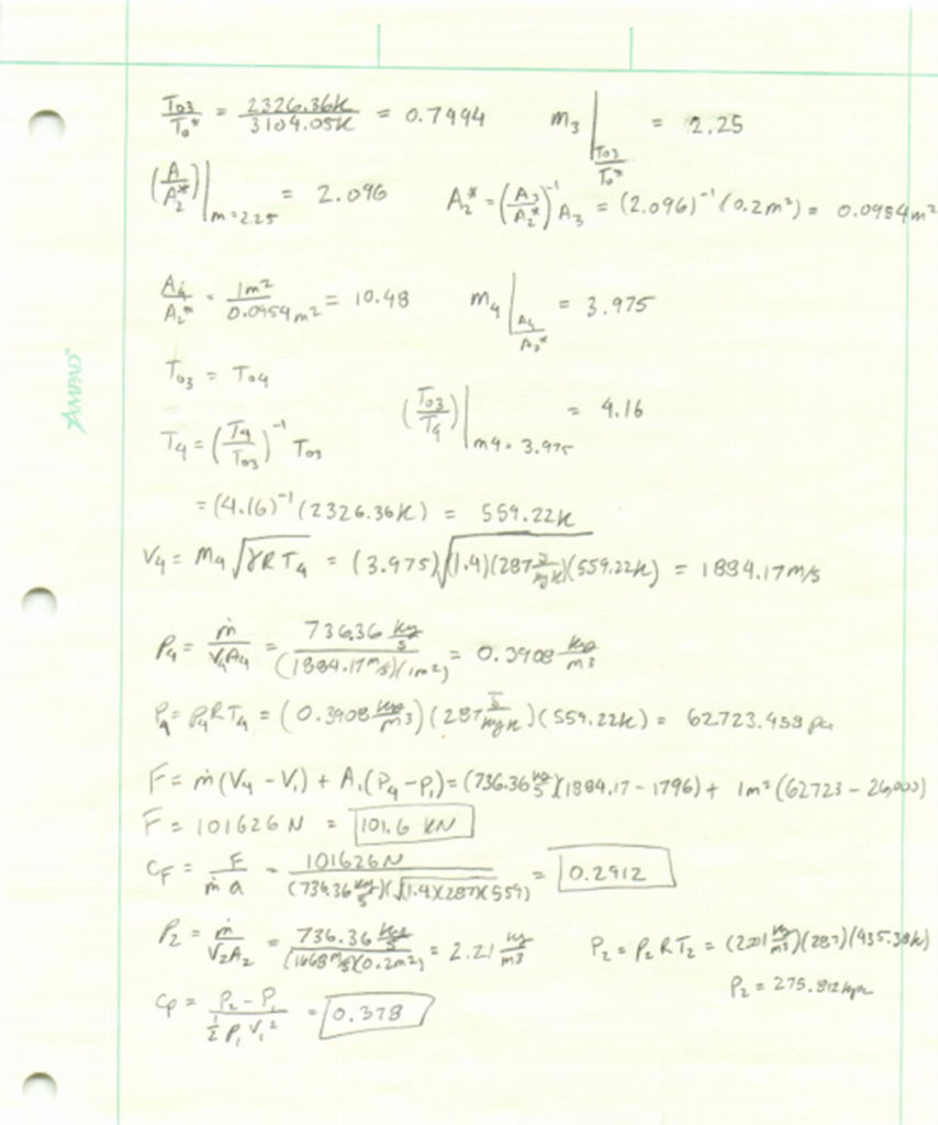
Hand Calculations
Matlab solution: