Automotive Half Shaft Design
Introduction
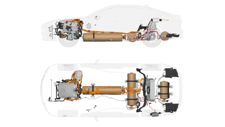
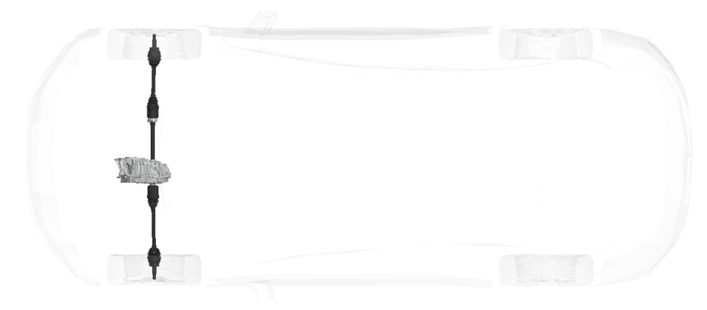
The half shaft—also known as a drive axle or constant velocity (CV) axle—is a fundamental component in the power delivery system of modern vehicles. It connects the differential or transaxle to the wheels, transmitting torque while accommodating suspension travel and steering motion. In front-wheel-drive (FWD) and all-wheel-drive (AWD) vehicles, a pair of half shafts work in unison, each transmitting power to one wheel, completing the link between the drive unit and the road.
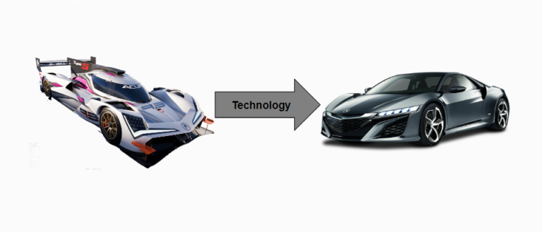
Commercial half shafts are typically over-designed to ensure reliability under a wide range of operating conditions. However, in performance or research applications, engineers often develop custom half shafts to reduce mass and rotational inertia, both of which have a measurable impact on acceleration and handling.

Half shafts are commonly designed by predicting the applied torsional loads and selecting inner and outer diameters such that the resulting shear stress does not exceed the material’s yield strength. Multiple combinations of diameters can meet the same load requirement, but designers aim to minimize both mass and rotational inertia for optimal dynamic performance. Because the mass and rotational inertia of a hollow shaft are inversely related, both cannot be minimized simultaneously; thus, reducing one typically increases the other. As a result, engineers must make a careful trade-off between weight and inertia to achieve the best overall vehicle performance.
Purpose and Importance
The primary purpose of the half shaft is to transfer rotational power from the drive unit (DU) to the wheels, enabling vehicle motion. However, the half shaft plays several critical roles in overall vehicle dynamics:
- Torque transmission — Ensures consistent delivery of power from the differential to the driven wheels.
- Suspension compliance — Allows the wheel to move vertically while maintaining torque transfer.
- Steering articulation — In front-drive configurations, it permits angular movement during cornering.
- Vibration control — Proper half-shaft stiffness minimizes driveline vibrations and noise.
- System durability — High fatigue resistance prevents failures under repeated load cycles.
Half shafts and drive units (DU) are highly sensitive to vehicle mass and tire outer diameter. Increasing either mass or tire size increases the torque required to achieve the same acceleration, thereby demanding stronger shafts, joints, and powertrain components to maintain performance targets.
Vehicle Mass, Tire Diameter, and Load Sensitivity
Vehicle mass (kg) and tire outer diameter (Dtire) directly affect both torque loading and dynamic performance:
- A heavier vehicle requires a higher tractive force (F=ma) to meet the same acceleration target (e.g., 0–60 mph).
- A larger tire diameter increases the torque demand at the wheel: T=F×Dtire/2. Thus, larger tires amplify the stress experienced by the half shaft.
- To maintain performance, the half shaft and drive unit must be sized with stronger materials and larger cross-sectional areas.
Abuse loads—transient torque spikes from aggressive acceleration, traction loss, or driveline shocks are also influenced by vehicle architecture and drive unit inertia. A system with a high-inertia drive unit or greater vehicle mass experiences higher torque reactions, emphasizing the need for robust half-shaft design.
Half Shaft Sizing Fundamentals
Half shaft sizing is based on two main torque sources:
- Skid torque (traction-limited torque) — determined by tire-road friction and vehicle dynamics.
- Powertrain torque (drive unit-limited torque) — determined by engine or motor capability.
Skid Torque Calculation
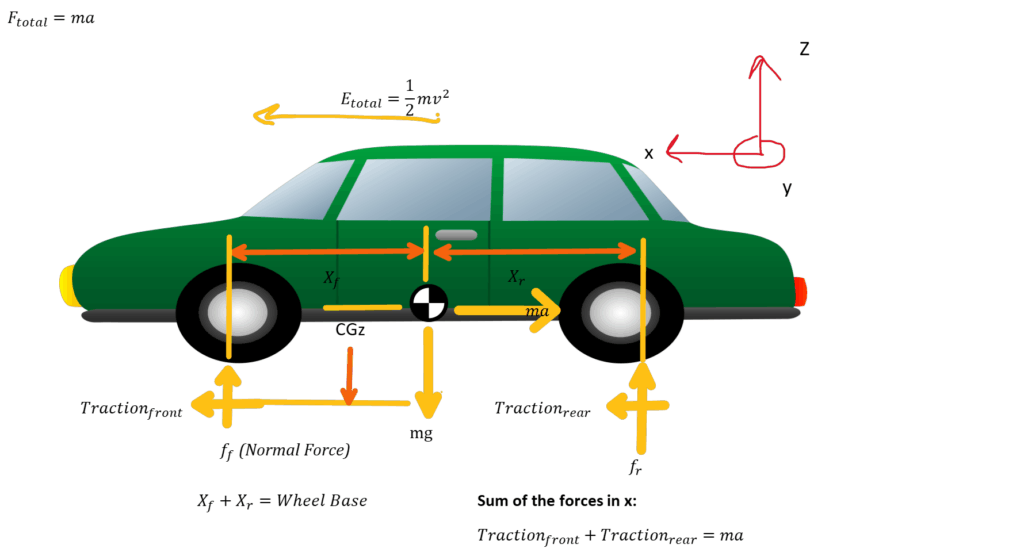
Using longitudinal dynamics and static equilibrium, the normal forces at each axle are:
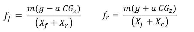
Where:
- m — vehicle mass (kg)
- g — gravity
- a — acceleration
- CGz — center of gravity height (m)
- Xf,Xr — distances from CG to front/rear axles (m)
- L = Xf+Xr — wheelbase (m)
The maximum tractive torque at the wheels (before slip) is given by:

where μ is the friction coefficient and Rtire is the tire’s effective rolling radius.
These skid torque values are critical for defining the design envelope of the half shaft.
Strength and Fatigue Design
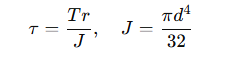
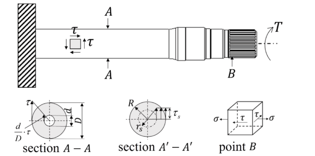
Once torque loads are determined, the half shaft is analyzed as a torsional member.
For a solid circular shaft:
The allowable shear stress must satisfy:
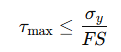
where σy is the material yield strength and FS is a safety factor (typically 1.5–2.5).
Fatigue life is then evaluated using cyclic torsional loading combined with bending stresses due to wheel motion.
Advanced designs employ finite element analysis (FEA) and dynamic torque simulations to account for:
- Shaft geometry optimization (hollow vs. solid)
- Joint angles during suspension and steering motion
- Rotational inertia effects on launch performance
Influence on Acceleration (0–60 mph)
The 0–60 mph acceleration time (t0−60) reflects how effectively the half shaft and drive unit can transmit torque to the ground. It is approximated by:
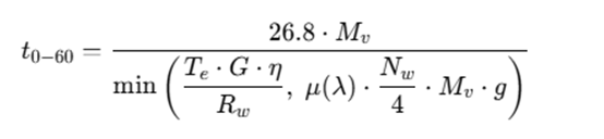
where:
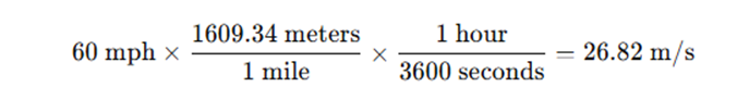
- V is final velocity (60mph ≈26.8 m/s)
- η is the drivetrain efficiency (~0.7)
- Mv is the mass of the vehicle (kg)
- Te is engine shaft torque (Nm)
- G is total gear ratio (Gear x final drive)
- Rw is the radius of the wheels (m)
- Nw is the number of driving wheels (typically 2 or 4)
- g is gravity (9.81 m/s2)
- μ is the friction coefficient between the tires and the road (~0.9, but can vary by ground surface)
- 4 is the total number of wheels a vehicle has (held constant for the majority of vehicles on the road)
Since F=ma, any increase in mass directly increases the required torque and lengthens the acceleration time. Similarly, a larger tire radius (Rtire) demands higher torque for the same acceleration—again highlighting the strong dependency of half shaft sizing on vehicle mass and tire diameter.
Failure Modes and Symptoms
Half shafts experience both steady and shock loads; when compromised, they can produce several noticeable symptoms:
- Vibration or Shuddering — due to imbalance, bent shafts, or CV joint degradation.
- Clicking During Turns — a sign of worn or damaged CV joints.
- Loss of Power Transmission — complete failure can immobilize the vehicle.
- Grease Leakage or Torn Boots — leads to joint contamination and accelerated wear.
Because half shafts are directly tied to vehicle safety and mobility, inspection of the CV boots and joints during routine maintenance is essentialhalf shaft questions.
Conclusion
Half shafts are vital mechanical links between the powertrain and the road. Their design balances stiffness, flexibility, and fatigue resistance under dynamic conditions. The process of half-shaft sizing—driven by skid torque or powertrain torque, and heavily influenced by vehicle mass, tire diameter, and drive unit inertia—ensures that performance targets such as 0–60 mph acceleration are met without compromising durability.
As vehicles become heavier and more powerful (especially with electric drive units), understanding and optimizing these relationships is crucial for achieving efficiency, safety, and performance.
References
Junlou Li et all. (2024). Lightweight design and analysis of automotive drive shafts. Structures, 60, 107507. https://doi.org/10.1016/j.istruc.2024.107507
Skid Torque Equation Derivation