Network Communication Plan
The Network Communication Plan Library from the Network Layout Floor Plans Solution.
Do you need to draw a network layout floor plan, network topologies diagram, network topology mapper, or a network communication plan similar to this sample? Usually, the process of planning and designing of network communication plans and other listened types of plans is sufficiently complex. But now, this process is maximally facilitated, you can use a predesigned sample or template from the selection provided through ConceptDraw Store, the predesigned vector objects of network and communication elements and devices offered in quantity at the libraries. The physical topology depicts the placement of different network components, devices and cables, the interconnections between the network nodes and cabling. On this Network Communication Plan is used a cable Cat5e, which is one of the types of cables used to transmit the signals and comprised of four twisted pairs. Usually, Cat5e cable is unshielded and is used in structured cabling for computer networks such as Ethernet.
Ethernet Cable Layout
The Network Communication Plan Library from the Network Layout Floor Plans Solution.
This network layout floor plan example visualizes an Ethernet Cable Layout diagram that is a “UGA Technical Network Liaison Handbook” based on the data from the website of the University of Georgia. Ethernet is a common family of computer networking technologies of organization the local area network (LAN), the packet transfer of data for computer network and larger networks. The Ethernet standards determine the wiring and electrical signals at the physical level. Ethernet uses the concept of shared broadcast; each computer sends the data to this broadcast and indicates to whom they are addressed. The data can reach all computers on the network but are handled only one to whom they are intended, another computers ignore the data of others. Currently the Ethernet standard almost always involves connection through a switch, in this case the data reach only to the addressee, which greatly increases the speed of work and network security.

Network Floor Plan Layout
The Network Communication Plan Library from the Network Layout Floor Plans Solution.
The Ethernet physical layer, which is a component of Ethernet family of computer network standards, was developed over a long time period and includes several physical media interfaces and magnitudes of speed. The speed range depends on the type of cable (this can be bulky coaxial cable, the twisted pair or optical fiber cable) and takes the values from 1 Mbit/s to 100 Gbit/s. At this, the network protocol stack software works almost similarly on all physical layers. This sample represents in detail a Network Floor Plan Layout and shows a plan of an Ethernet computer network that will be constructed using a category 5 cable (Cat 5e). Cat 5e is a twisted pair cable for carrying signals. It is convenient to use callouts to convey the additional information for a viewer of this plan and it is a good idea to visually indicate the cable type on a callout.
Network Equipment Layout and Cabling
The Network Communication Plan Library from the Network Layout Floor Plans Solution.
The development of the mounting plan of the network connections and location of the network equipment in buildings of organizations, as well as the development of plans of the laying the cable lines between the buildings require a lot of special knowledge, attention from the specialists and experts at this field, and it is also desirable the availability of a special software for professional designing the network diagrams, plans and schematics. An important role for the plan composition plays the length and number of floors at the building, location of premises and the placement of network equipment inside the building, all these parameters determine the kinds of network devices and the type of cable needed to be used for installation. This sample diagram demonstrating the network equipment layout and cabling was designed using the tools of Network Layout Floor Plans solution for the best network visualization and network mapper software ConceptDraw DIAGRAM

First Floor Ethernet LAN Layout Floor Plan
The Network Communication Plan Library from the Network Layout Floor Plans Solution.
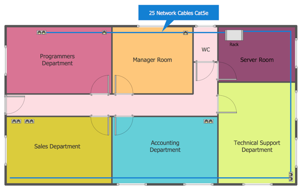
A Local Area Network (LAN) is a network that covers some small area like a room, office, bank, business center, or any other premises or building. Today, the most commonly used LAN is Ethernet, which lets to transmit the data over a LAN with a speed of a gigabit per second, uses the bus or star topology and is based on the technology of multiple access with a carrier sense and collision detection (CSMA/CD). The Ethernet is a standard that uses the principle of random access to the shared environment, which can be a coaxial cable, twisted pair, fiber optic cable, and radio waves. This sample is the Ethernet LAN Layout on the typical office floor plan. There are represented all office departments on this diagram, the arrangement of computer equipment, network devices and cabling at the office premises. Each department’s room is colored with its own color for more visablility.

Second Floor Office Network Layout
The Network Communication Plan Library from the Network Layout Floor Plans Solution.
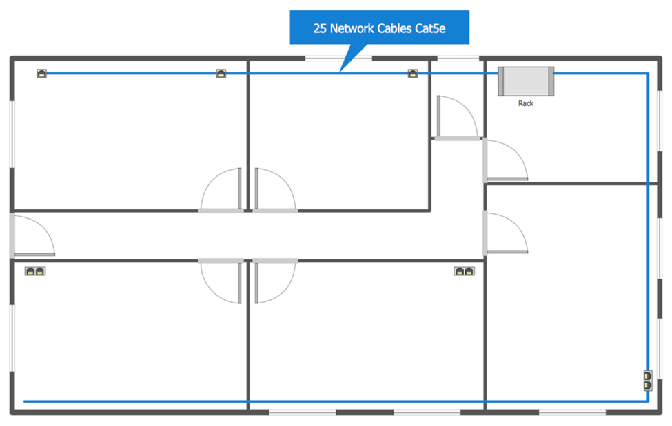
How to build a network within the office premise? It is necessary to start from designing the plan or sketch of the projected network. The main task when developing such project is to choose the best path for mounting the cables from the workplaces and for the placement the switch. A huge role plays the type of premise, its layout, material and thickness of walls, so in each particular case it is necessary to make an individual plan. Furthermore, the beforehand thoughtful plan helps to avoid the errors at the stage of purchase the network equipment and materials, as well as further laying of cables and installation of network equipment. This sample shows detailed network layout floor plan at the office building with many rooms. If your office building is a multi-floor, the ConceptDraw DIAGRAM software lets design the similar plans for all floors of your building in a few minutes.
Third Floor Network Layout Plan
The Network Communication Plan Library from the Network Layout Floor Plans Solution.
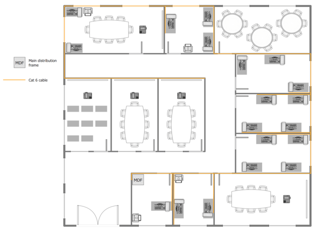
The Network Layout Plan on the third floor at the office building with use of Cat 6 cable, which is a standardized twisted pair cable for Ethernet and also other network physical layers, and is compatible with the Category 3 and Category 5/5e cable standards. You can see two identical working premises with large quantity of workplaces on this floor. The quantity of such premises maybe even more in several times, but it is not a problem for ConceptDraw DIAGRAM software, which assists in drawing the plans of any complexity for the buildings of any area and quantity of floors. The placement of cabling, servers and other network equipment with respect to the firewalls and computers greatly affects the network productivity and security, that is why it is needed to be taken seriously and thoroughly the questions of choosing the cable type, of creation the network layout plans and implementing them.

| Network Budget Items | Quantity | Amount |
| Cat 5 Cables SL600 CAT5e 1000ft Premium | 100×99.99$ | 10,999 |
| Patch Cables and panels | 3000×30.99$ | 92,970 |
| Printer (Richo5054 Workgroup printers) | 10 x 1,999$ | 20,000 |
| Laptop’s dell latitude | 50×990$ | 49,500 |
| Desktops AIO HP | 50×799$ | 39,950 |
| Switches (cisco meraki Mx64) | 15x 415$ | 7,225 |
| Firewall CATEO | 2x 3,000$ | 6,000 |
Total Network Budget: – 206,645
References:
https://www.conceptdraw.com/solution-park/computer, h.-p. (2022, 05 18). Conceptdraw. Neworkdigrams, pp. 1-6.