Phasors in AC Circuits
AC circuits are a big deal in the world of electrical engineering. They power up our homes, gadgets, and pretty much everything around us. Capacitors and inductors in AC circuits cause timing shifts between voltage and current waves. Phasors clarify this relationship between voltage, reactance, impedance, and current. Phasors are like the superhero sidekick that helps you make sense of AC circuits.
What Are Phasors?
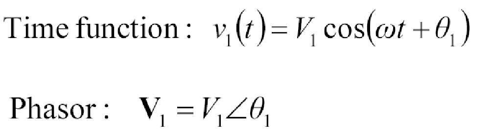
In physics and engineering, a phasor is a complex number that represents a sinusoidal function with a fixed amplitude (A) and initial phase (θ), and a constant angular frequency (ω). This concept is part of a broader idea called analytic representation, which breaks down a sinusoid into the product of a complex constant and a time/frequency-dependent factor. The complex constant, representing amplitude and phase, is known as a phasor, complex amplitude, sinor, or complexor in older texts.
What are the phasors in AC circuits?
Phasors are akin to polarity in DC circuits, indicating the “directions” of voltage and current waveforms in AC circuits. Analyzing AC circuits comprehensively requires using this mathematical representation. Phasors are rooted in complex numbers, combining “real” and “imaginary” components.
Phasor diagrams visually depict the size and directional correlation among multiple alternating quantities. The vertical element of phasors symbolizes the variables undergoing sinusoidal fluctuations in a particular equation, like voltage (v) and current (i).
Why phasor are used for AC circuits?
Analyzing AC circuits can be complex due to the sinusoidal variations of voltage and current, often out of phase. Phasors, complex numbers representing the magnitude and phase of sinusoidal signals, simplify this analysis.
Imagine you have a merry-go-round spinning at a constant speed. Now, if you take a picture of the merry-go-round every few seconds, you’d capture its position at different points in time. Well, phasors are kind of like that, but for AC sinusoidal waveform. They represent the magnitude and phase of an AC voltage or current. Instead of dealing with messy time-domain AC signals, we get to work with neat phasor representations.
Representing AC Signals with Phasors
Now, don’t worry about all the technical jargon. Converting those sinusoidal AC signals into phasors is like taking a screenshot of the signal at a specific moment. This snapshot gives us all the essential info we need to understand the AC circuit behavior without getting bogged down in complicated math.
How do you draw a phasor diagram for an AC circuit?
The phasor diagram is plotted with time zero (t = 0) along the horizontal axis. The lengths of the phasors on the diagram correspond proportionally to the values of voltage (V) and current (I) at the moment the diagram is drawn.
Understanding Complex Numbers
Okay, now you might be wondering, “Complex numbers? What’s that got to do with phasors?” Well, they’re like peanut butter and jelly. Complex numbers help us represent phasors in a tidy way, kind of like coordinates on a map. And you know what’s cool? You can even represent phasors in a polar form, which is a breeze to work with!
Phasor Arithmetic and Operations
Here’s where things get super fun! Do you know how you can add, subtract, and multiply regular numbers? Guess what? You can do the same with phasors! By accurately drawing two phasors to scale on graph paper, their sum, V1 + V2, can be found by measuring the length of the diagonal line, known as the “resultant r-vector,” from the origin to the intersection of the constructed lines. However, this graphical method can be time-consuming. For a more precise approach, an analytical method can be used. This method involves finding the vertical and horizontal components of the resultant vector, VT, by applying the cosine and sine rules.
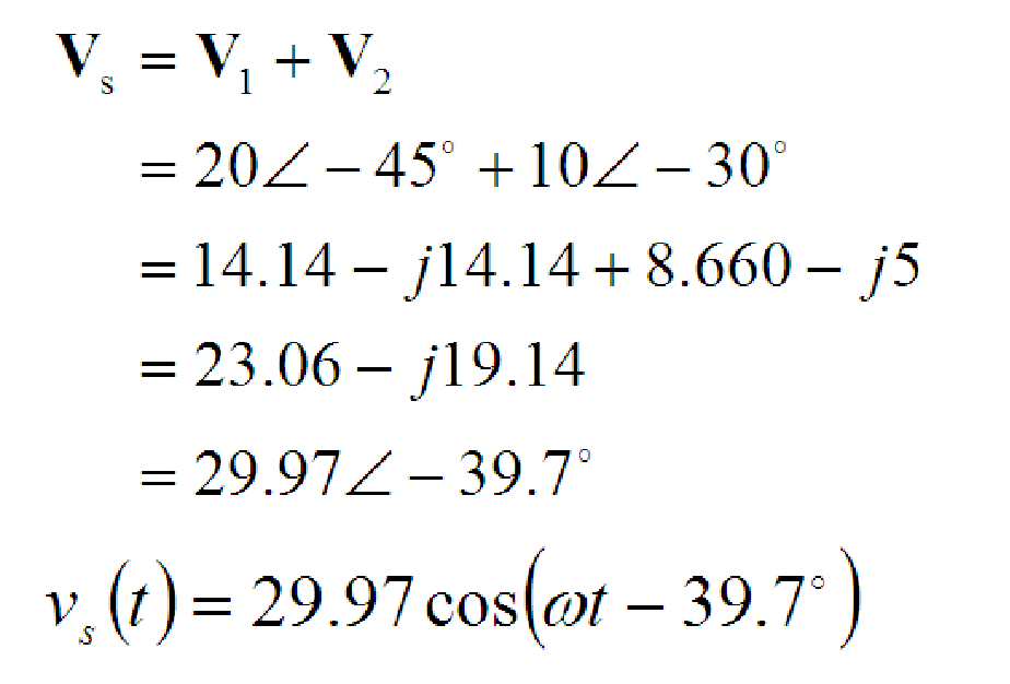
What is phasor addition?
Phasor addition is a mathematical operation that combines two or more phasors in AC circuit analysis. It involves adding their magnitudes and considering their phase angles to obtain a single resultant phasor, representing the combined effect of the original phasors.
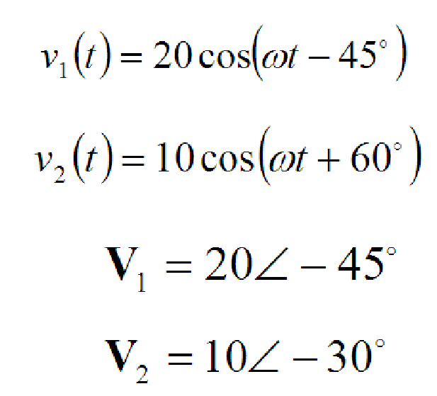
Example Problem:
Adding the two Voltages:
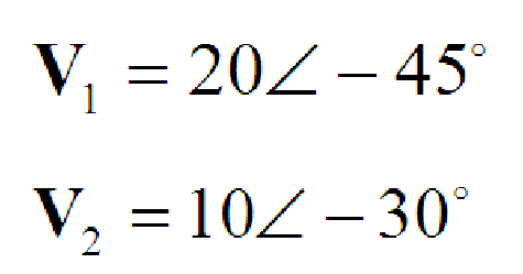
Solution:
Kirchhoff’s Laws in Phasor Form
We can apply KVL and KCL directly to phasors. The sum of the phasor voltages equals zero for any closed path. The sum of the phasor currents entering a node must equal the sum of the phasor currents leaving.
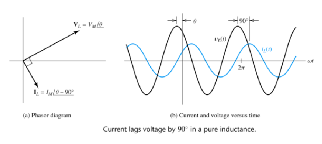
What is the relationship between voltage and current in an AC inductive circuit?
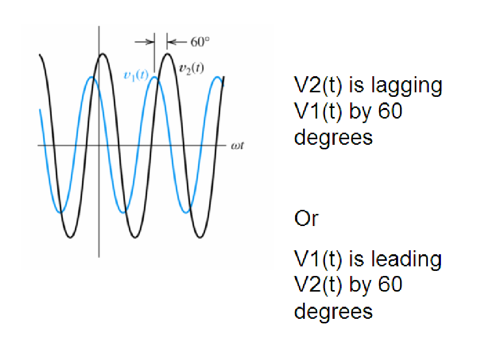
In an AC inductive circuit, the voltage and current are out of phase, with the current lagging behind the voltage by one-fourth of a cycle, or by a 90º phase angle. This phase difference occurs due to the inductance, and the relationship between voltage and current is governed by the impedance, which combines the effects of resistance and inductive reactance.
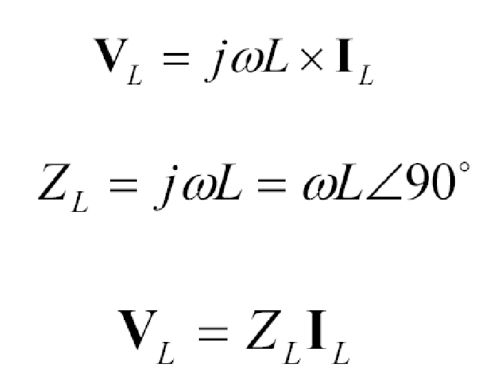
How do you find the complex impedance of an inductor?
To find the complex impedance of an inductor in an AC circuit, use the formula ZL = jωL, where ZL is the complex impedance, j represents the imaginary unit, ω is the angular frequency of the AC signal, and L is the inductance of the inductor in henries.
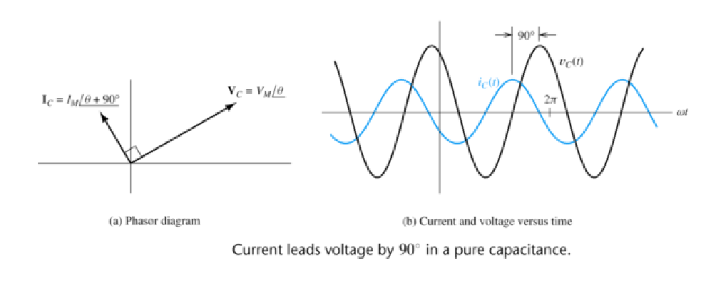
What is the relationship between voltage and current in an AC capacitor circuit?
In an AC capacitor circuit, the current leads the voltage by 90 degrees one-fourth of a cycle due to the capacitive reactance. The relationship between voltage and current is governed by the impedance, which depends on the frequency of the AC signal and the capacitance of the capacitor.
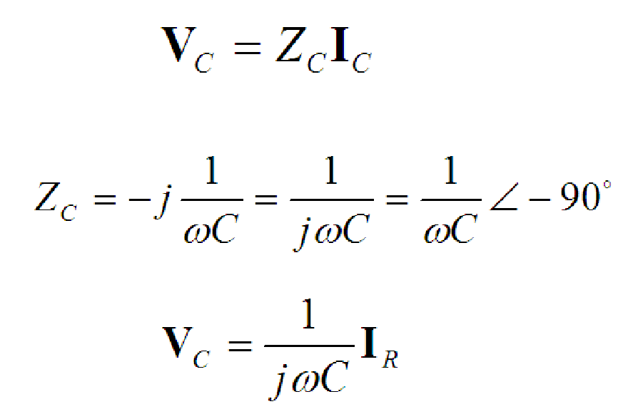
What is the complex impedance of a capacitor?
The complex impedance of a capacitor in an AC circuit is given by ZC = 1 / (jωC), where ZC is the complex impedance, j represents the imaginary unit, ω is the angular frequency of the AC signal, and C is the capacitance of the capacitor in farads.
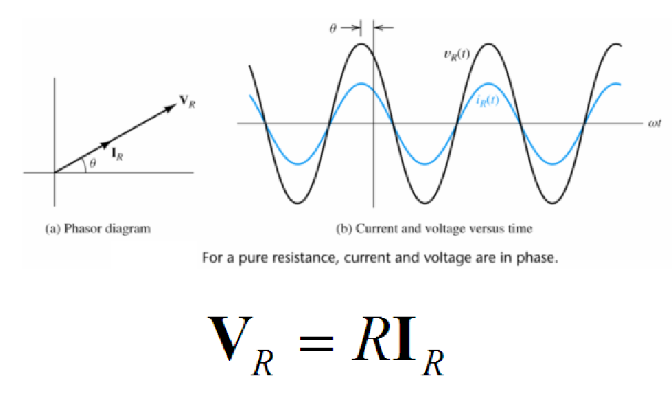
How do you find the voltage across a resistor in an AC circuit?
To find the voltage across a resistor in an AC circuit, use Ohm’s law: VR = IR * R, where VR is the voltage (in volts), IR is the current flowing through the resistor (in amperes), and R is the resistance of the resistor (in ohms). For a pure resistance load, current and voltage are in phase in an AC circuit.
AC Circuit Examples and Applications
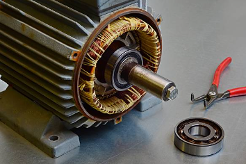
Phasors aren’t just some theoretical mumbo-jumbo. They have real-world applications! From power transmission to electric motors, phasors play a crucial role in electrical engineering and power systems.
Examples
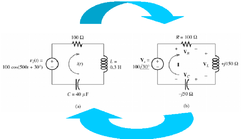
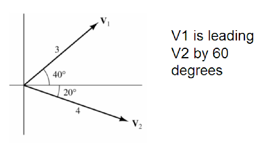
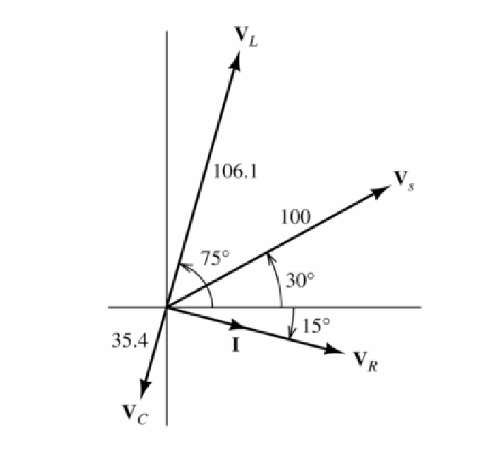
Phasors diagram based on AC Circuit above
Conclusion
In conclusion, phasors are invaluable tools for understanding and analyzing AC circuits. They simplify complex calculations by straightforwardly representing sinusoidal quantities, allowing engineers to easily determine magnitudes, phases, and relationships between voltages and currents. Phasors, rooted in the concept of complex numbers, provide a bridge between the theoretical and practical aspects of AC circuit analysis, making them essential for anyone working with alternating current systems.