
AC Motor: How It Works, Types, Speed & Power Formulas
An AC motor is an electric motor powered by alternating current (AC) that typically comprises two main components. The outer stator contains coils that receive AC to create a rotating magnetic field, while the inner rotor, connected to the output shaft, generates a second rotating magnetic field. The rotor’s magnetic field can be generated by permanent magnets, reluctance saliency, or DC or AC electrical windings. AC linear motors, though less common, operate on the same principle as rotating motors but have their stationary and moving parts aligned linearly, producing linear motion instead of rotational motion.

What Is an AC Motor?
AC stands for “alternating current,” electricity that switches direction cyclically. Picture a coil of wire sitting in a magnetic field: when alternating current flows through the coil, it generates a magnetic field of its own, and the interaction between the two fields causes the coil to spin. In an AC motor, the armature is stationary rather than rotating, as it is in a DC motor — so there’s no commutator or brushes, and the rotor circuit generates its own excitation. AC motors fall into two main families: induction motors and synchronous motors.
A Brief History of the AC Motor
Alternating current technology traces back to the 1830–1831 discovery by Michael Faraday and Joseph Henry that a changing magnetic field can induce an electric current (Faraday is typically credited, due to his earlier publication). In 1832, Hippolyte Pixii built a basic form of AC generator with the first alternator. Elihu Thomson expanded on this in 1886 with an AC motor, and in 1887, Charles Schenk Bradley patented a two-phase AC power transmission system. Independently, Galileo Ferraris and Nikola Tesla invented “commutatorless” AC induction motors — Ferraris demonstrated a single-phase motor in 1885, and Tesla showcased a two-phase model in 1887.
Induction Motors: The Workhorse of AC Propulsion
Induction motors are the workhorses of AC propulsion systems. They’re electric motors that operate on a simple yet ingenious principle: electromagnetic induction, driven by a rotating magnetic field generated from alternating current.

As the stator’s magnetic field changes direction, it induces a current in the rotor, creating a magnetic field of its own. These two fields interact, generating the rotational force that sets the motor in motion.
Types of Induction Motors
There are two main categories of induction motors: single-phase induction motors, which start up when you flip a switch and are common in household appliances, and three-phase induction motors, the workhorses of industrial applications.
How Does a 3-Phase AC Motor Work?
A three-phase AC motor generates a rotating magnetic field in its stator windings using alternating current. This changing field induces currents in the rotor, and the interaction between the stator and rotor fields creates the rotational force that drives the motor. In operation, the stator current induces a magnetic field that causes the rotor to rotate, with:
- Three phase windings, spaced 120 degrees apart
- Three-phase voltage (current) fed into the windings

AC Motor Construction Types
There are two main types of AC motor construction:
- Stator construction
- Laminated iron core with slots
- Coils are placed in the slots to form a three-phase or single-phase winding
- Squirrel-cage rotor construction
- Laminated iron core with slots
- Metal bars are molded into the slots
- Two end rings short-circuit the bars
- The bars are slanted to reduce noise

How AC Motors Generate a Rotating Magnetic Field
The rotating magnetic field at the heart of an AC motor comes from a choreographed interaction between the stator and rotor. The stator’s windings create a magnetic field when AC flows through them. This field induces currents in the rotor, which in turn produces a counteracting magnetic field. The interaction between these two fields creates the force that spins the rotor — energy transfer in its purest form.
Types of AC Motors
There are several types of AC motors, each with its own characteristics and applications:
Single-Phase AC Motor
Single-phase AC motors are used in locations with a single-phase power supply. These motors are smaller and more affordable, typically designed for fractional-kilowatt capacities. Powered by a single-phase AC electrical supply, they differ from three-phase motors by having one main and one auxiliary winding, positioned perpendicular to each other. The rotor moves in response to the combined effect of two oppositely rotating fields, following the principle of the double-revolving field theory, which results in equal and opposite torque.
Polyphase AC Motor
Polyphase motors, such as two- or three-phase AC motors, differ from single-phase motors in that their stator poles are not aligned, so the rotor passes by them at different times. These motors operate on a polyphase system, where equal voltages at the same frequency have a phase difference between adjacent electromagnetic fields. The most common polyphase system is three-phase, which produces 1.5 times more output than single-phase systems. Unlike the pulsating current of single-phase systems, current from polyphase systems remains constant.
Synchronous Motor
Synchronous motors operate at a constant speed that’s synchronized with the frequency of the AC power supply. They have higher efficiency than induction motors and are often used in applications where precise speed control is required, such as industrial machinery and robotics.
Reluctance Motor
Reluctance motors achieve a precise rotating magnetic field without needing to run at synchronous speed. They produce torque through reluctance — a form of torque generated in iron devices when an exterior magnetic field induces an inner field, with torque produced when the low-reluctance path is oriented at an angle to the poles of the outer field.
Hysteresis AC Motor
The rotor of a hysteresis motor sets it apart from other AC motors, since it contains a semi-permanent magnetic material. Torque is generated by the lag between magnetic flux and the external magnetizing force, with eddy currents contributing to the motor’s torque. Hysteresis motors offer precise speed control with minimal flutter and run quietly. The rotor has a non-magnetic core with a special magnetic material layer, forming a smooth, windingless cylinder typically made of chrome or steel with a hysteresis loop.
Repulsion Motor
A repulsion motor, a type of single-phase motor, operates on the principle of repelling like poles. In addition to a rotor and stator, it includes a commutator-brush assembly. The rotor has a distributed DC winding connected to the commutator, similar to a DC motor, but with the carbon brushes short-circuited. Short-circuiting the rotor circuit allows it to receive power from the stator through transformer action, and the motor turns as like poles — north and north, south and south — repel each other.
Asynchronous Motor
An asynchronous motor relies on induced current in its rotor to create rotational movement, making it the most common type of AC motor. AC power is connected to the stator, with all power going to the stator and none directly to the rotor. The rotor is induced by its proximity to the stator’s electromagnetic field, which generates its own field and causes rotation. Lacking brushes or slip rings, asynchronous motors are highly efficient and reliable, and their simple, robust design makes them a favorite for heavy-duty applications.
Each type of AC motor has its own advantages and disadvantages, making different types suitable for different applications based on their specific requirements.
What Are AC Fields?
An AC magnetic field is generated when a coil carries alternating current. This current, typically in the form of a sine wave, introduces time-based changes to the magnetic field. The equations below apply to a three-phase AC machine.

What Does the Air Gap Do in an AC Motor?
Analogous definitions apply to AC and DC electrical machines here. As defined by the Electro-Mechanical Authority (EASA), the air gap in an AC machine is the space between the rotor core and the stator. This gap is a key element of motor design and affects both the strength of the magnetic circuit and overall motor efficiency.

Synchronous Speed and Slip
Synchronous speed — the theoretical speed of rotation — is determined by the frequency of the AC power supply and the number of poles in the motor. But in the real world, perfection is a myth: enter “slip,” the difference between synchronous speed and the actual speed of the rotor. Slip is essential — it’s what generates the force that drives the motor.

AC Motor Speed Formula: Synchronous Speed vs. Number of Poles
The synchronous speed of an AC motor is set by the source frequency and the pole count. To compute RPM, multiply the frequency by 60 and divide by the number of pole pairs:
Ns (RPM) = (60 × f) / P
where f is the supply frequency in hertz and P is the number of pole pairs. For example, a motor with 2 pole pairs (4 poles) run on a 60 Hz supply has a synchronous speed of (60 × 60) / 2 = 1,800 RPM.

What Is the Relation Between Slip and Frequency?
As the rotor accelerates, the relative velocity between the rotor and the rotating magnetic field diminishes. Consequently, the slip (s) — and with it, the rotor current frequency — decreases. Calculating slip frequency involves measuring the phase angle covered within a set interval; once that phase angle measurement is available, slip can be determined by driving the output to an accurately calibrated timer.

What Forces Act on an AC Motor?
Electric motors experience multiple forces during operation. The electromagnetic force, generated by the interaction between the stator and rotor fields, initiates motion. Friction opposes motion, and load torque resists the motor’s rotational force. Together, these forces determine the motor’s performance and efficiency.
The rotating field induces a current in each rotor bar, and the interaction between that current and the field generates the driving force:
F = BLIr
where B is the magnetic flux density, L is the length of the rotor conductor, and Ir is the induced rotor current.

Speed-Torque Characteristics of AC Motors
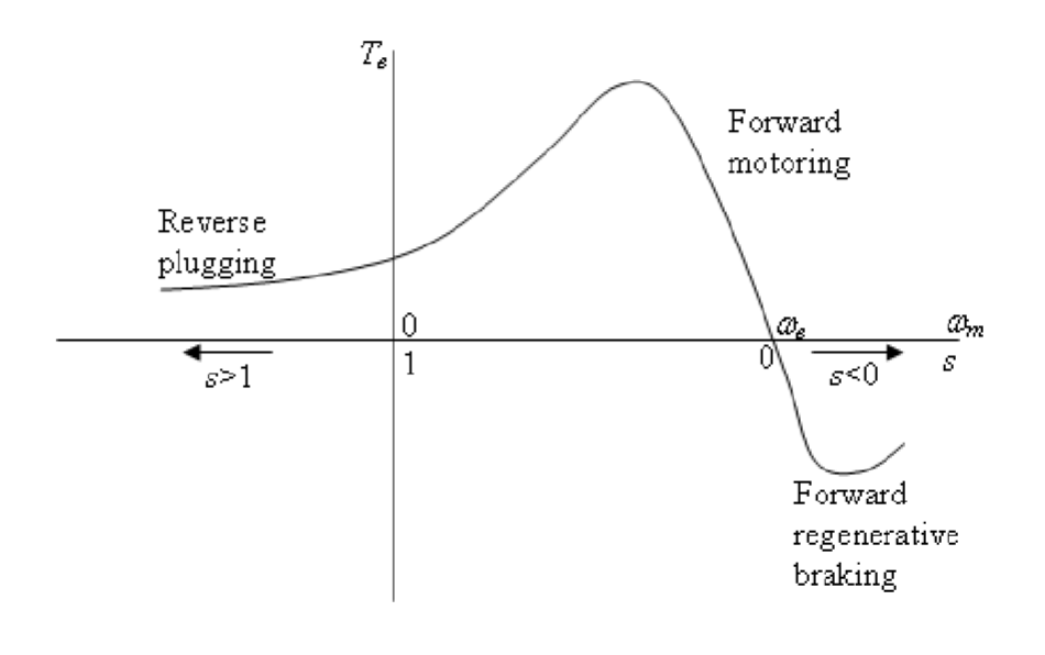
Speed-torque characteristics describe a motor’s performance profile: how much torque it can provide starting from rest, and how that torque changes as it speeds up. The answers lie in the speed-torque curve, which reveals a motor’s performance capabilities and helps engineers choose the right motor for a given task. Motors are usually operated at low slip to keep the speed-torque relationship more linear and maximize efficiency.
Speed Control Methods for Induction Motors
There are two main methods:
- Stator terminal voltage control
- Stator frequency control
A power electronics converter is usually required for either method.
Drawbacks of Variable Stator Voltage Control
Variable stator voltage control has two main drawbacks:
- Harmonics. Excessive harmonics and back EMF arise, particularly in delta connections, causing elevated losses and motor overheating.
- Torque. The stator voltage control method yields considerably low starting torque.

Why Keep the V/f Ratio Constant in Induction Motors?
V/f control of an induction motor means changing the motor’s speed by adjusting frequency while holding a constant voltage-to-frequency (V/f) ratio. This is crucial for preserving the motor’s air gap flux and maintaining steady torque output across the speed range.

What Is the VVVF Method of Speed Control?
VVVF stands for Variable Voltage Variable Frequency, a technique implemented by a variable frequency drive (VFD) and widely used to control induction motor speed. By maintaining a constant V/f ratio, VVVF prevents the frequency at which motor core saturation occurs from shifting, ensuring effective speed control across the motor’s operating range.

AC Motor Power Formula
An AC motor’s mechanical output power is the product of torque and angular speed:
P = T × ω
where P is power in watts, T is torque in newton-meters, and ω is angular speed in radians per second. For a three-phase motor, the electrical input power drawn from the supply is:
P = √3 × VL × IL × cos φ
where VL and IL are the line voltage and line current, and cos φ is the motor’s power factor. The difference between electrical input power and mechanical output power accounts for the motor’s internal losses — a motor’s nameplate efficiency rating describes how much of that input power actually reaches the shaft as usable work. Nameplate power ratings are typically given in kilowatts (kW) or horsepower (HP), where 1 HP ≈ 0.746 kW.
AC Motor Applications
AC motors are used across an enormous range of consumer and industrial equipment, including:
- Consumer and residential: fans, washing machines, HVAC blowers and compressors, refrigerators, power tools, and vacuum cleaners
- Industrial: conveyor systems, industrial pumps and compressors, CNC machinery, elevators and escalators, and large ventilation fans
- Specialized: synchronous motors in robotics and precision machinery, three-phase induction motors in heavy industrial drives, and AC traction motors in some electric and hybrid vehicles
Induction motors in particular dominate industrial use because of their simple, rugged construction, lack of brushes or slip rings, and low maintenance requirements.
AC Motor vs. DC Motor: What’s the Difference?
AC and DC motors both convert electrical energy into mechanical motion, but they differ fundamentally in how they’re powered and controlled. An AC motor runs on alternating current and generates its rotating magnetic field directly from that alternating supply, which is why most AC motors — induction motors especially — need no brushes or commutator. A DC motor runs on direct current and typically relies on a commutator (or, in brushless designs, electronic commutation) to keep the rotor turning.
In practice, AC motors tend to be simpler, more rugged, and lower-maintenance — a major reason they dominate industrial and heavy-duty applications — while traditional brushed DC motors offer simpler speed control and strong starting torque, which has historically made them popular in smaller, precision, or battery-powered applications. For a closer look at how DC motors are built and controlled, see our guide to DC motor design.
Advantages and Limitations of AC Motors
AC motors, and induction motors in particular, offer several advantages: a simple, rugged construction with no brushes or commutator to wear out, low maintenance requirements, high reliability, and straightforward operation directly from the AC grid. They’re generally more cost-effective than comparable DC motors at larger power ratings, which is a major reason they dominate industrial applications.
Their main limitations are around speed control: standard induction motors run at a speed set largely by the supply frequency and pole count, so precise variable-speed control requires additional equipment such as a variable frequency drive. Starting torque can also be lower than some DC motor designs, and very precise speed or position control generally requires a synchronous motor or a motor paired with closed-loop control electronics.
Frequently Asked Questions About AC Motors
What is an AC motor used for?
AC motors power everything from household fans, washing machines, and HVAC systems to industrial pumps, compressors, conveyors, and CNC machinery. Induction motors in particular are the default choice for most industrial drive applications.
What is the formula for AC motor speed?
Synchronous speed is Ns (RPM) = (60 × f) / P, where f is the supply frequency in Hz and P is the number of pole pairs. The motor’s actual speed is slightly lower than synchronous speed due to slip.
What’s the difference between an AC motor and a DC motor?
AC motors run on alternating current and generate their rotating field directly from the AC supply, so most need no brushes or commutator. DC motors run on direct current and typically use a commutator — or electronic commutation in brushless designs — to keep the rotor turning.
What is slip in an AC induction motor?
Slip is the difference between a motor’s synchronous speed and its actual rotor speed. It’s essential to motor operation — slip is what induces current in the rotor and generates the torque that drives the motor.
How is AC motor power calculated?
Mechanical output power is P = T × ω (torque times angular speed). Electrical input power for a three-phase motor is P = √3 × VL × IL × cos φ. The difference between the two reflects the motor’s internal losses.
Key Takeaways
The next time you plug in a vacuum cleaner or marvel at the precision of industrial machinery, remember the AC motor working behind the scenes. Its ability to harness alternating current and convert it into motion is a testament to more than a century of engineering refinement — from the induction motor’s simple, rugged design to the carefully choreographed dance of magnetic fields that makes every type of AC motor turn.
Whether you’re an engineer specifying a motor for a new design or simply curious how the devices around you work, understanding induction, synchronous, and specialty AC motor types — along with the speed, slip, and power formulas that govern them — gives you a solid foundation for the electromagnetism that keeps the modern world running. For how direct current motors compare, see our guide to DC motor design.
Discover more from Engineering Cheat Sheet
Subscribe to get the latest posts sent to your email.


