Exterior and Mechanical Package Analysis of a Corvette- Front Compartment
Background of Chevrolet Corvette:
The first generation (C1) Chevrolet Corvette made its official debut on January 17, 1953, making it one of the longest-running nameplates in automotive history. The Corvette was the first American-made sports car and was created to compete with the European sports cars which the American soldiers became accustomed to while overseas during WWII. The current generation Corvette is commonly referred to as the C8 as it is the 8th generation to be produced. The Corvette is a two-seater luxury sports car, which provides performance for a fraction of the cost of its competitors. Most of the C8 Corvette owners are in their 40s – mid50s while customers in their 30s saw a 25% increase in sales compared to the previous generation (C7). The states which have the highest registrations of corvette are California, New York, Texas, and Florida. Most Corvette owners have another vehicle, which is considered their daily driver, and buy a Corvette to have some extra fun on the weekends at the track.

| Vehicle Dimensions | 182″ L x 76″ W x 49″H |
| 0-60 | 2.8 |
| MSRP | $79,850 |
| Max Speed | 205 mph |
| Fuel Economy | 16 City / 24 Highway |
| Horsepower | 495 hp |
| Vehicle Mass | 3,535 lbs |

Systems, sub-systems, and components in the Chevrolet Corvette:
The project will focus on the exterior and mechanical packaging for the front end of the Corvette. Below is a pictorial representation of where all the parts in the specified compartment fall in a vehicle. The list of systems/subsystems and components can be found at the top of the following page:


Estimate number of components (crude estimate):
The approximate number of individual components in the front compartment we selected is 100 broken up among all the different subsystems, are in the front end of the vehicle.
List of other systems that have interfaces with the front compartment of the Corvette:
| Other systems that interface w/ the front compartment |
| Front Closure (hood) |
| Front Suspension |
| Power Train |
| Brake system |
| Front Fender |
| Windshield |
| Side Closure ( Door) |
| Aero (air shingles) |
What is an interface diagram?
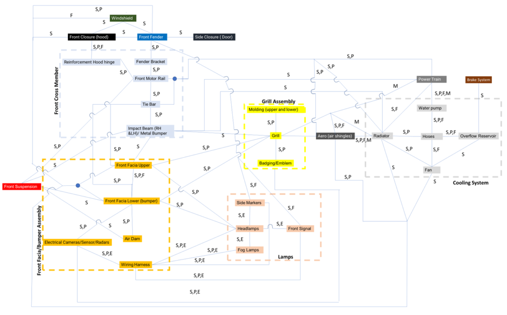
An interfaces diagram is a visual overview of the interface relations between different components in a product. Using an interface diagram allows a complex system with multiple components to be simplified and broken down into a flowchart that helps visualize how various systems, subsystems, and components interface with each other. Below is an interface diagram of the front compartment of the Corvette.

What is an FMEA interface matrix?
An interface matrix is a tabular representation of an interface diagram, the goal of the interface matrix is to quickly review the interfaces between subsystems and/or components. The interface matrix below shows how the components in the vehicle’s front end of a Corvette interact with each other.
- s = spacial interface
- p = physical interface
- e = electrical interface
- m = material flow interface
- I = informational interface
- f = functional interface
| 1 | 2 | 3 | 4 | 5 | 6 | 7 | 8 | 9 | 10 | 11 | 12 | 13 | ||
| Front fascia/bumper | Front cross members | Grill | Lamps | Radiator | Front Closure (hood) | Front Suspension | Power Train | Brake system | Front Fender | Windshield | Side Closure ( Door) | Aero (air shingles) | ||
| 1 | Front fascia/bumper | S,P | S,P | S,P,E | S | S | S | – | – | S,P | F | – | S,P | |
| 2 | Front cross members | S, P | S | – | S, P | S,P, F | S, P | S, P | – | S,P | – | – | S,P | |
| 3 | Grill | S, P | S | – | M | – | – | M | M | – | – | – | S,P,F | |
| 4 | Lamps | S,P, E | – | – | – | – | – | – | – | S,P | – | – | – | |
| 5 | Radiator | S | S, P | M | – | S | – | S, P,M,F | S | – | – | – | S,P,M,F | |
| 6 | Front Closure (hood) | S | S,P,F | – | – | S | – | S | S | S | S | – | – | |
| 7 | Front Suspension | S | S,P | – | – | – | – | S | S,P | – | – | – | – | |
| 8 | Power Train | – | S,P | M | – | S,P,M, F | S | S | S | – | – | – | I | |
| 9 | Brake system | – | – | – | – | S | S | S, P | S | – | – | – | – | |
| 10 | Front Fender | S,P | S,P | – | S,P | – | S | – | – | – | – | S | – | |
| 11 | Windshield | F | – | – | – | – | S | – | – | – | – | – | – | |
| 12 | Side Closure ( Door) | – | – | – | – | – | – | – | – | – | S | – | – | |
| 13 | Aero (air shingles) | S,P | S,P | S,P,F | – | S,P,M,F | – | – | I | – | – | – | – |
After analyzing the interface diagram and matrix it can be concluded that many of the components have the same relationship (to other components/subsystems) as other components within the same subsystem. The subsystems and components in the front fascia/bumper chunk had a lot of spatial and physical relationships but not too many functional, material/fluid, or information interactions. Other chunks, like the engine, or fuel system would have more of these interactions. From these observations, it can be concluded that a chunk with fewer interactions would be easier to package.
The interface matrix tells us the most complex components/subsystems to package are the front fascia/bumper, front cross members, powertrain, and front closure. With the exception of the powertrain, these are not necessarily the components I would expect to have the greatest number of interactions, therefore the most complexity. This complexity is due to the material/fluid flow, allowing the engine to breathe.
One takeaway from the diagram and matrix was the importance of understanding material/fluid flow. Components with Material/Fluid flow interactions need special attention when being designed. Any material or fluid flow must be contained in the intended area, ensuring it doesn’t cause damage to any components that are not meant to be exposed to these materials or fluids. These components also need to be designed so the material/fluid flows in the proper direction, sometimes utilizing gravity for this movement. Taking time to consider this flow will ensure the fluid/material will flow between the correct components, in the correct direction.
Another takeaway is the spatial/physical interactions. With so many parts being packaged in such a small area this is important, especially with moving components, hot components, and sharp components. Each component needs to be specially considered to understand every interaction it might have during the life of a vehicle. These spatial/physical interactions also impact the assembling of the components. If there is not sufficient space, the operator will take longer to install, or even injure themselves.
Each of the components in the diagram/matrix is exposed to outside environments. This might include rain, snow, sun, wind, salt, dirt, etc. These variables are not included in the matrix/diagram, but they are still important things to consider when packaging. There are many things a packaging engineer has to consider, things that might be out of their control.
The biggest takeaway from the diagram and matrix is that a packaging engineer needs to be entirely aware of every component, subsystem, and system before beginning the design process. They also need to understand the function/needs of every component, ensuring every component will properly work together over the full life of the vehicle.
Package engineer’s considerations (issues including manufacturing/assembly, trade-offs) in designing this chunk:
A packaging engineer working on the front chunk will need to focus the most on components that have multiple interactions. The components that only have spatial or physical interactions will be the easier ones to package.
Any components that have electrical interactions will require special considerations. This includes wiring that runs between these components. When packaging wiring, there are a few special precautions that need to take place. This includes keeping the wiring dry at all times, preventing any repetitive rubbing on the wire, and any tight bends in the wire that will compromise the integrity over time. The manufacturing process of wiring also needs to be considered. The wiring needs to be assembled at a time in the manufacturing process where it can be routed with ease, most likely toward the beginning of the process.
The cross members and many other metal components in this vehicle are stamped and welded together, revealing many rough edges. All wire routing needs to maintain at least a 10mm clearance to these edges. The wire routing also needs to stay out of the way of any moving parts. If the wire gets pinched in these parts, it will quickly become ineffective.

Another important consideration when packaging this system is heat. There is heat produced by the radiator and the lamps. All plastic components or heat-sensitive components need to maintain significant clearance to these parts to prevent melting.
There are a few moving parts in this chunk, including the fan for the radiator. The package engineer needs to ensure everything maintains proper clearance to this moving part, to avoid damaging any components. Another consideration is the assembly process. Many of these components are manually assembled into the vehicle, and the tighter they are packaged the more difficult it is for the operator. To prevent any slower assembly times, it is important to make sure there is hand clearance for every part that needs to be assembled. This hand clearance also needs to include part variability. The parts the operator is installing all have a tolerance stack up. It is important to understand this, again to ensure the operator can do their job as efficiently as possible.

The hood (including hood hinge reinforcement) and bumper interaction act as a waterproofing barrier to the elements. When considering the packaging of the front end of the vehicle it is important to make sure nothing under the hood can get wet. This is especially important in the winter. If water gets between the hood and bumper it could freeze, removing your access to the components under the hood.
Another consideration when designing the front end “chunk” is the type of paint. All exterior-facing components are exposed to harsh UV rays and need paint that is capable of withstanding this over time. The underside of the vehicle is exposed to salt, sand, and general road debris. The best paint to withstand these elements should be used on these components.
Possible changes or improvements to the front compartment of a Corvette:
For the cluster selected during this project in addition to ensuring all the components fit nicely together in the allotted space, it would be a good idea to also consider the following criteria for the front-end chunk: Aerodynamic performance: The front facia of the vehicle is the first to interact with the air and a poorly integrated front end can cause a bigger or bulker front facia leading to poor vehicle fuel economy. Also balancing the grill opening for engine airflow versus the negative drag impacts from the grill opening should be considered while packaging these components.

safety requirements: The front end of a vehicle must be designed and packaged in a way where in the case that there is a collision with a pedestrian, the pedestrian is pushed up onto the hood and not down underneath the vehicle.
Cost impacts: Cost is another key factor in any design which was not taken into consideration during this project. The biggest way to positively impact cost is by reducing the number of components and fasteners in each of the sub-systems. Another way to positively affect the cost is by placing components in areas close to where they need to be (improving design efficiency). An example of this is reducing the length of all your wiring and cooling hoses by enabling the straight path possible.
Design of manufacturing: DFM is very important and is something that was also out of the scope of this project. An example of this is when engineers decide if a component should be assembled on the assembly line or if should they be brought in as a pre-assembled sub-system. Looking at reducing the number of parts in each of the sub-systems enables a more efficient streamlined manufacturing process and as a result, also helps free up some space in the front end of the vehicle.
Mass efficiency: Most of the mass in the front end of the vehicle will come from the suspension and front cross members which are part of the Body-in-White (BIW). However, the front cross members are the components primarily responsible for carrying the loads in the event of a front-end collision. The front end of the vehicle must ensure that it meets FMVSS 208 front barrier crash safety test. By packaging all the front end in a way that allows for the front bumper and impact beams to have a consistent cross-section, the overall vehicle BIW will be more efficient leading to reduced mass.
Exterior aesthetics: Finally for this cluster of parts styling is extremely important (primarily on all the class A components). A good-looking vehicle gets potential customers in the showroom. Even though beauty is subjective it is something that must be taken into consideration while packaging this part of the vehicle and would be good to incorporate it into the packaging analysis.

Lessons learned from the above analyses of the front motor compartment:
One of the most notable things that were noticed during this project was how integral the front facia is to the front compartment of a vehicle. The front facia acts as the central hub which interfaces with all other subsystems in the area. The electrical components (lamps/ sensors cameras) and grill assembly mount directly to the front facia. The front facia sub-system must then attach to the body-in-white (tie bar and fender) via mechanical fasteners such as clips and bolts.
At first, you might not realize how many other systems and components the front facia interacts with, but it becomes much more obvious once an interface diagram is created and you can visually see all the interfaces the subsystems in the front cluster interact with. What is most interesting is to see interfaces for components that are not even touching such as the grill to the brakes and power train. Both the brakes and power train depend on the openings on the front grill to cool off the brake disk and engine coolant.
Reference:
- https://www.motortrend.com/features/15-vehicles-with-the-longest-running-nameplate/
- https://gmauthority.com/blog/2022/03/2022-corvette-stingray-with-carbon-fiber-accessories-live-photo-gallery/
- https://www.datamasters.org/corvette-owners/#:~:text=Demographics%20for%20Corvette%20Owners&text=The%20largest%20age%20group%20(12,nearly%2055%25%20of%20sales).
- https://gmauthority.com/blog/2022/09/national-corvette-museum-and-bowling-green-assembly-resume-plant-tours/


