SAE International – Motor Vehicle Drivers’ Eye Locations (SAE J941)
Foreword – This SAE Recommended Practice describes the eyellipse, a statistical representation of driver eye locations, which is used to facilitate design and evaluation of vision in motor vehicles. Examples of eyellipse applications include rearview mirror size and placement, wiped and defrosted areas, pillar size and location, and general exterior field of view. These applications are covered in other SAE and ISO practices.
This revision of the eyellipse is the most significant update to SAE J941 since its inception. The new eyellipses differ from the old eyellipses in the following ways:
- The axis angles in plan view and rear view are parallel to vehicle grid.
- The side view x-axis angle is tipped down more at the front.
- For the 95 percentile eyellipse (99th shown in parentheses):
- The x-axis length is 7.5 (18.9) mm longer.
- The y-axis is 44.6 (63.6) mm shorter.
- The z-axis is 7.4 (10.1) mm longer.
- The centroid location is generally higher and more rearward.
- The centroid location in side view is a function of packaging geometry (SgRP, steering wheel location, seat cushion angle, and the presence or absence of a clutch pedal).
- The eyellipse is no longer positioned according to the drivers’ design seat back angle.
- The eyellipse for seat tracks shorter than 133 mm in length has an x-axis length unchanged from the prior SAE J941. The y and z axis lengths, and the centroid location, are based on the new values/ equations given in this document.
- Neck pivot (P) and eye (E) Points are based on the previous plan view sight lines to rearview mirrors and A-pillars, but are adjusted to the shape and location of the new eyellipses.
New additions, incorporated as appendices to this document, are summarized as follows:
a. Fixed seat eyellipses for the United States user population at a 50/50 gender mix and 95 and 99% tangent cutoffs (Appendix B).
b. A procedure for calculating adjustable and fixed seat eyellipses for any user population stature and gender mix at selected percent tangent cutoffs. (Appendices A and C).
c. Tables providing comparisons between tangent cutoff eyellipses and inclusive eyellipses. An eyellipse of inclusion can be constructed using these tables (Appendix D).
Eyellipses for Class B vehicles are unchanged from prior versions of SAE J941 (Appendix E). Appendices are informative only and are not normative requirements of this document
Scope
This SAE Recommended Practice establishes the location of drivers’ eyes inside a vehicle. Elliptical (eyellipse) models in three dimensions are used to represent tangent cutoff percentiles of driver eye locations.
Procedures are provided to construct 95 and 99% tangent cutoff eyellipses for a 50/50 gender mix, United States user population.
Neck pivot (P) points are defined in Section 6 to establish specific left and right eye points for direct and indirect viewing tasks described in SAE J1050. These P Points are defined only for the adjustable seat eyellipses defined in Section 4.
This document applies to Class A Vehicles (Passenger Cars, Multipurpose Passenger Vehicles, and Light Trucks) as defined in SAE J1100. It also applies to Class B vehicles (Heavy Trucks), although these eyellipses have not been updated from previous versions of SAE J941.
The appendices are provided for information only and are not a requirement of this document.
References
2.1 Applicable Publications—The following publications form a part of this specification to the extent specified herein. Unless otherwise indicated, the latest issue of SAE publications shall apply.
2.1.1 SAE PUBLICATIONS—Available from SAE, 400 Commonwealth Drive, Warrendale, PA 15096-0001.
SAE J826—Devices for use in Defining and Measuring Vehicle Seats and Seating Space
SAE J941 (1997)—Motor Vehicle Drivers’ Eye Locations
SAE J1050—Motor Vehicle Driver and Passenger Head Position
SAE J1100—Motor Vehicle Dimensions
SAE J1516—Accommodation Tool Reference Point
SAE Paper 650464—Automobile Driver Eye Position, J.F. Meldrum (1965) SAE Paper 720200—Driver Head and Eye Positions, D.C. Hammond and R.W. Roe (1972)
SAE Paper 750356—Describing the Driver’s Workspace Eye, Head, Knee, and Seat Positions, R.W. Roe (1975)
SAE Paper 852317—Describing the Truck Driver Workspace, N.L. Philippart and T.J. Kuechenmeister (1985) (in SAE SP 712)
2.2 Related Publications—The following publications are provided for information purposes only and are not a required part of this specification.
2.2.1 SAE PUBLICATIONS—Available from SAE, 400 Commonwealth Drive, Warrendale, PA 15096-0001.
J1517—Driver Selected Seat Position
SAE Paper 680105—The Eyellipse and Considerations in the Driver’s Forward Field of View, W.A. Devlin and R.W. Roe (1968)
SAE Paper 980012—Development of an Improved Driver Eye Position Model, M.A. Manary, et al (1998) (in SAE SP-1358)
M.S. Sanders (1983), “U.S. Truck Driver Anthropometric and Truck Workspace Data Survey,” Final Report submitted to SAE, Warrendale, PA
B.E. Shaw and M.S. Sanders (1984), “Female U.S. Truck Driver Anthropometric and Truck Workspace Data Survey,” Final Report submitted to SAE, Warrendale, PA
2.2.2 OTHER PUBLICATION—Available from UMTRI, RIPC, 2901 Baxter Road, Ann Arbor, MI 48109-2150. Email: [email protected], 734-764-2171.
W.A. Devlin (1975), “Visibility Design Guide,” Proposed SAE Recommended Practice (also, ISO/ TC159/ SC4(USA1)6), SAE Driver Vision Committee, Troy, MI
Definitions
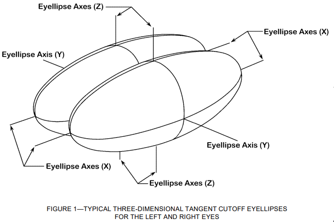
3.1 Eyellipse—A contraction of the words eye and ellipse used to describe the statistical distribution of eye locations in three-dimensional space located relative to defined vehicle interior reference points. See Figure 1.
3.2 Cyclopean Eye or Mid-Eye Point—Mid-point between left and right eye points and/or left and right eyellipse centroids at centerline of occupant.
3.3 Tangent Cutoff Plane—Plane tangent to an eyellipse.
NOTE— When projected at a specified angle or to a specific target, a tangent cutoff plane may be considered a sight plane. In a two-dimensional view, a sight plane may be considered a sight line. See Figure D1 in Appendix D.
3.4 Tangent Cutoff Eyellipse—Three dimensional eyellipse derived as the perimeter of an envelope formed by an infinite number of planes dividing the eye locations so that P percent of the eyes are on one side of the plane and (100 – P) percent are on the other. See Appendix D.
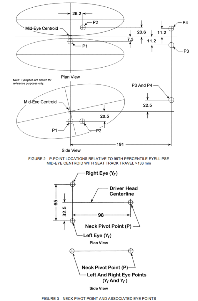
3. 5 Neck Pivot Points (P Points)—Points about which a driver’s head turns on a horizontal plane. See Figure 2.
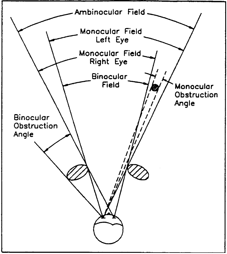
3.6 Neck Pivots, P1 and P2—Neck (head) pivot points used to position eye points for measuring the driver binocular obstruction due to A-pillars at the left and right side of the vehicle. See Figure 2.
3.7 Neck Pivots, P3 and P4—Neck (head) pivot points used to position eye points for measuring driver field of view from rearview mirrors located to the left and right of the driver. See Figure 2.
3.8 Eye Points (E Points)—Two points representing the left and right eyes of the driver, used in conjunction with a Neck Pivot Point to describe specific viewing tasks. See Figure 3.
3.9 Inclusive Eyellipse—Eyellipse that contains a specified percentage of drivers’ eyes inside its boundaries.
3.10 Dimensions and Definitions in SAE J826 and SAE J1100
a. H-POINT
b. SEATING REFERENCE POINT, SgRP
c. PEDAL REFERENCE POINT (PRP)
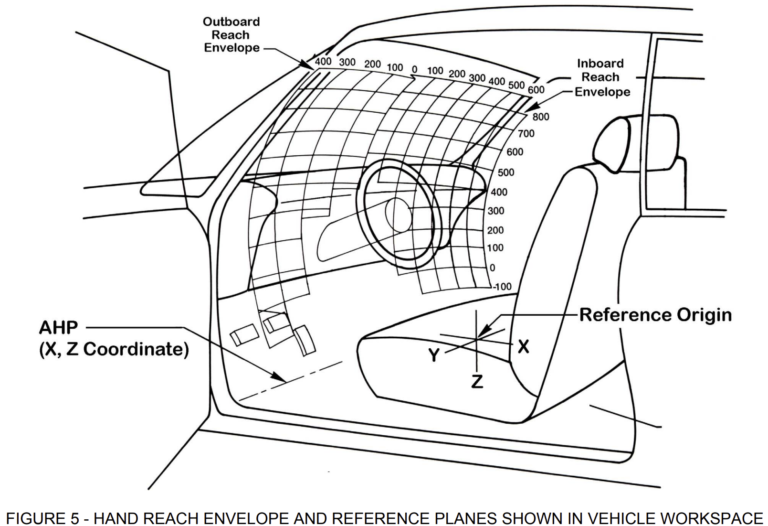
d. ACCELERATOR HEEL POINT (AHP)
e. H-POINT TRAVEL PATH
f. A19 — SEAT TRACK RISE
g. H30 — SEAT HEIGHT
h. L6 — PEDAL REFERENCE POINT (PRP) TO STEERING WHEEL CENTER
i. CLASS A and CLASS B VEHICLES
Adjustable Seat 95 and 99% Tangent Cutoff Eyellipses for the United States User Population at a 50/50 Male/Female Gender Mix
These eyellipses are based on the user populations described in Table 1. Driver eyellipses for a 50/50 gender mix shall be used for designing Class A vehicles.

The 95 and 99% tangent cutoff eyellipses for a 50/50 gender mix are constructed from tables and equations given in 4.1 through 4.2.1. These eyellipses are applicable to driver and front outboard passenger seat locations.
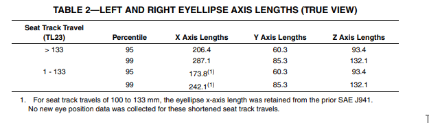
4.1 Axis Lengths—Axis lengths are given in Table 2. See Figure 4.
4.2 Axis Angles—The eyellipse is aligned with the vehicle axes in plan view (Z plane) and rear view (X plane), but it is tilted down at the front in side view (Y plane). 4.2.1 SIDE VIEW ANGLE, β—In side view the angle of the eyellipse is

Eyellipse Locating Procedure, Class A vehicles
5.1 Determine seat characteristics A19, W20, H30.
5.2 Determine H8 and L6.
5.3 Determine t based on the percentage of vehicle production that has a clutch pedal. If 50% or more of anticipated production has a clutch pedal, set t=1. Otherwise, set t=0.
5.4 Construct identical left and right eyellipses based on the axes given in Table 2. Locate the centroids using Equations 2, 3, and 4.
5.5 Tilt the front of the eyellipse x-axis down in side view according to Equation 1.
Neck Pivot (P) and Eye (E) Points: Locating Procedure, Class A Vehicles
These points are defined to simplify application of the eyellipse for specific viewing tasks requiring head and eye rotation in plan view. (See SAE J1050.) Neck pivot (P) points provide a plan view head rotation pivot center so the left and right eye (E) points can be repositioned for these specific viewing tasks. These P points are derived from a 95th percentile, 50/50 gender mix eyellipse. To determine the P-points, tangents were constructed to a forward target (A-pillar or exterior rearview mirror). Each P-point was derived so that its left and right eye points were as close as possible to a tangent point on the surface of a 3D 95th percentile eyellipses. P-points were not developed for 99th percentile eyellipes.
6.1 Neck Pivot (P) Points—Locate these points relative to the cyclopean (mid-eye) eyellipse centroid using values given in Table 3. See Figure 2.
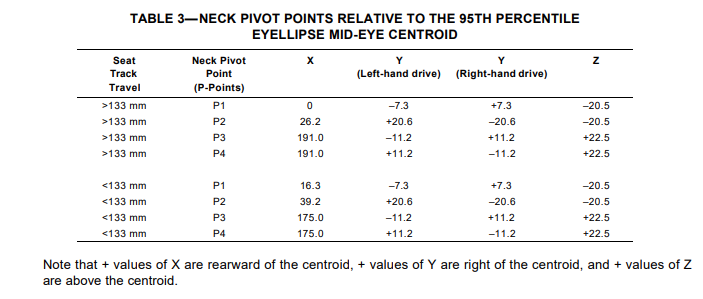
6.1.1 The X, Y, and Z values in the Table 3 may be added to Equations 2, 3, and 4, respectively, to obtain P Point locations relative to vehicle grid.
6.2 Eye (E) Points—Position the eye (E) points relative to the P points as shown in Figure 3 and the following equations:

Notes
7.1 Marginal Indicia—The change bar (l) located in the left margin is for the convenience of the user in locating areas where technical revisions have been made to the previous issue of the report. An (R) symbol to the left of the document title indicates a complete revision of the report.