Forces in Truss Members
Objective
To find and familiarize the stresses in the truss due to an externally applied load, and to see how geometry affects to stresses in the truss. Finally, the last goal of this experiment was to become familiar with strain gauge measurements.
Known & Assumptions:
Materials:
The materials required:
- The triangular trusses
- Tinius Olsen Testing Machine
- Strain gauge
- vernier calipers
- Safety glasses.
- Data acquisition unit (bridge)
- Computer
Procedures:
- Make sure you zero out the vernier calipers. Once calipers have been zeroed out, get a reading on the lengths of each of the links for each of the trusses. Recorded all readings reading.
- Based on the measurements for the length find the angles of the trusses and classify each accordingly.
- Theoretically calculate the stress in each of the members
- Connect the first truss to the Tinius Olsen Testing machine using the data acquisition unit.
- Put on safety glasses
- Start a program to record strain on the truss
- Apply five loads to the triangular truss, starting with the smallest. (all applied loads shall be equally spaced.
- After the final load has been applied remove the truss and repeat steps 4-7 with the remaining two trusses.
Equations/Givens
Theory:
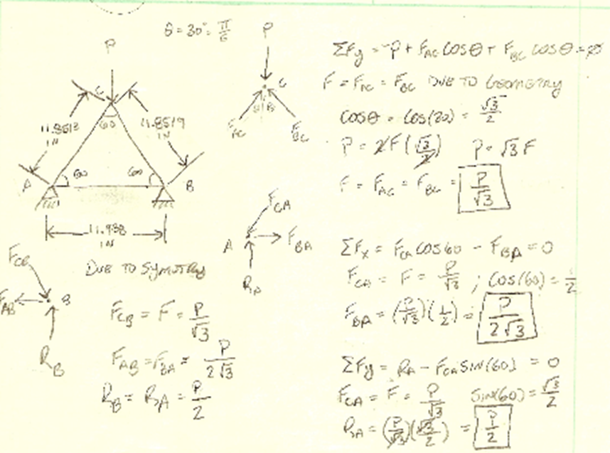
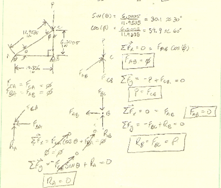
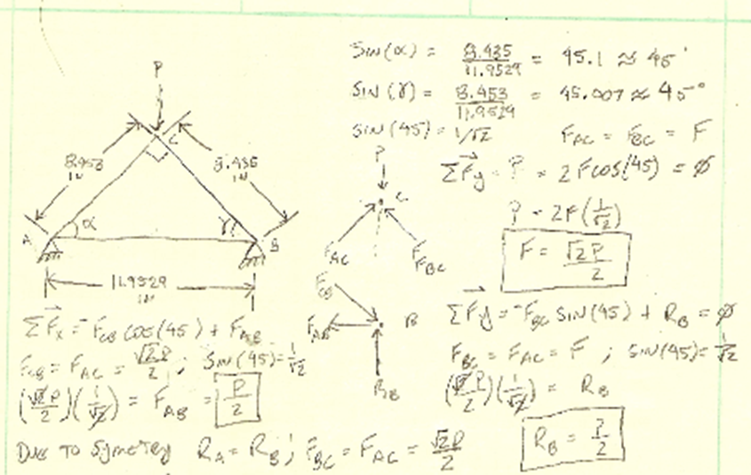
The theory behind this experiment is based on the statically determinate load and geometry of the trusses. You will calculate the theoretical stress in each of the members using the method of joints to compare theoretical data to actual data and see how the geometry and how load is applied affects the stress.
Equations:
Area (A):

Normal Stress(σ):

% error:

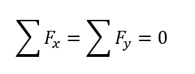
Equilibrium equations:
Show your work
Example calculations :
Area (A):

Normal Stress theoretical (σ):

Normal Stress theoretical (σ):

% error:

Graphs:
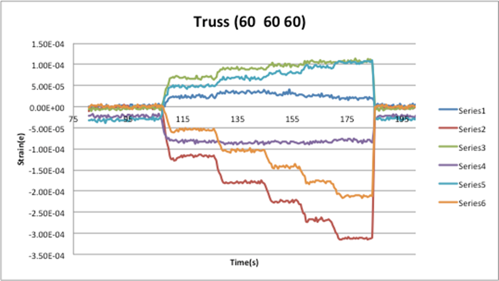
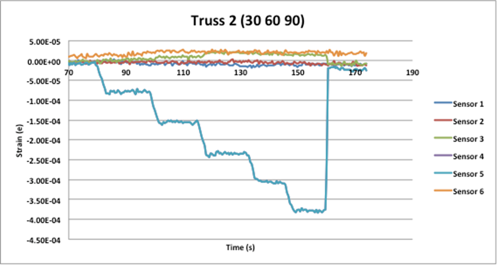
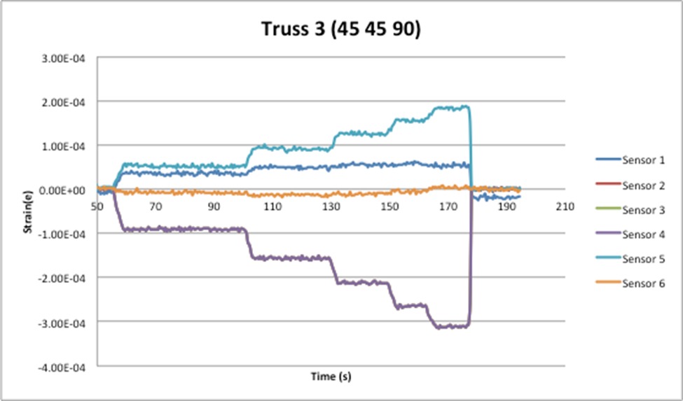
Data sets:


Answers
Findings:
After performing this experiment it was clear where the theatrical results sway away from the actual results. For the most part, the data was good where there the majority of the calculated vs theoretical results have less than a 20% error. With the 30 60 90 triangular truss there for the link AB and AC, I was unable to calculate the %error for the fact that theoretically both those links should be carrying 0 lbs, and you can not divide by 0. Even though I could not calculate the % error for this truss by reviewing the data you can compare how to truss BC which should be carrying 100% of the load is carrying the majority. For when 1250 lbf are applied to this truss BC carries 1113lbs AB and AC both carry less than 20lbf. With this being said when you compare such a large load of BC to the small loads carried by the other two links it can be said that those forces are negligible.
The only other link which had higher than usual %errors was link AB for the 45 45 90 triangular truss. As it was stated before the majority of the % errors are less than 20% whereas link AB in this truss % error ranged from 19%-40% which is relatively high when compared to the other members in the truss. Some of the possible reasons for this higher % error could have been if the strain gauge on this trust was not properly attached or if after multiple uses the strain gauge is not as accurate.
References:
person’s statics and strength of materials 7th edition, pg 480


