SAE J1517 – Driver Selected Seat Position
The following is a summary of SAE J1517.
Scope
A driver-selected seat position tool has been developed to estimate where drivers of varying sizes will place horizontally adjustable seats in different vehicle types. This tool uses equations that predict horizontal H-point (seat position) based on vehicle H-point height (H30) and steering wheel diameter (W9).
The tool provides equations for 2.5th through 97.5th percentile seat positions for Class A vehicles (passenger cars, vans, light trucks) with H30 under 405 mm and W9 under 450 mm.
For Class B vehicles (heavy trucks, some buses) with H30 between 405-530 mm and W9 between 450-560 mm, additional equations accommodate different male-to-female ratios in the driver population (50:50, 75:25, and up to 95:5).
The tool is designed both as a guide for designing horizontal seat travel and as a validation tool to check how well a seat track accommodates the target driver population.
References
The following publications are part of this specification:
SAE Publications:
- SAE J1100: Motor Vehicle Dimensions
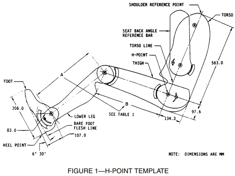
- SAE J1516: Accommodation Tool Reference Point
- “Driver Selected Seat Position Model” by Philippart, Roe, Arnold, and Kuechenmeister (1984), SAE Paper No. 840508
- “U.S. Truck Driver Anthropometric and Truck Workspace Data Survey” by M. S. Sanders (1983)
- “Female U.S. Truck Driver Anthropometric and Truck Workspace Data Survey” by B. E. Shaw and M. S. Sanders (1984)
The latest revisions of these publications are applicable unless otherwise specified.
Definitions
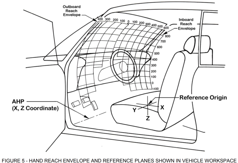
The definitions and equations outlined pertain to determining the driver-selected seat position for Class A vehicles. These vehicles use specific reference points and dimensions, including the H-point, H-point height (H30), steering wheel diameter (W9), accelerator heel point (AHP), and seating reference point (SgRP), as defined in SAE J1100.
- Class A Driver Selected Seat Position Lines: A series of curved, two-dimensional lines depict various driver seat positions behind the ball-of-foot reference based on different accommodation levels. These lines are calculated as a function of the vehicle’s H-point height using seven percentile-based equations.
- Accommodation Heel Reference Point: This is the point on the pedal plane where the depressed floor covering meets the area below the accelerator pedal. It serves as the horizontal reference for positioning the accommodation tool reference line and the driver-selected seat position lines for Class A vehicles.
The equations below provide seat positions for specific accommodation percentiles (2.5th through 97.5th) based on the height of the H-point above the heel reference point (H30).
| Percentile | Equation for Seat Position (x) |
|---|---|
| 97.5 | x = 936.6 – 0.613879z + 0.00186247z2 |
| 95 | x = 913.7 – 0.672316z + 0.00195530z2 |
| 90 | x = 885.0 – 0.735374z + 0.00201650z2 |
| 50 | x = 793.7 – 0.903387z + 0.00225518z2 |
| 10 | x = 715.9 – 0.968793z + 0.00228674z2 |
| 5 | x = 692.6 – 0.981427z + 0.00226230z2 |
| 2.5 | x = 687.1 – 0.895336z + 0.00210494z2 |
the definitions for seating accommodation in Class A and Class B vehicles:
Class B Vehicles’ Driver Selected Seat Position Lines: A series of lines in the side view that describe seat positions based on H-point height. Three sets of lines accommodate different male-to-female driver ratios (50:50, 75:25, and 90:10 to 95:5), which are calculated through specific equations.
Accommodation Ball of Foot Reference Point: A point on the pedal plane 203 mm from the heel reference point, serving as the vertical reference for positioning seat and workspace tools in Class A vehicles.
Pedal Plane: The line in the side view of the vehicle that is tangent to the accelerator pedal, representing the bottom of the manikin’s shoe.
Class A Vehicles’ Accommodation Tool Reference Line: A curved line in the side view that indicates a horizontal reference based on H-point height, used to position workspace tools for accommodating a 1:1 male-to-female driver ratio.
| Percentile | 50:50 Male-to-Female Ratio Equation | 75:25 Male-to-Female Ratio Equation | 90:10 to 95:5 Male-to-Female Ratio Equation |
|---|---|---|---|
| 97.5 | x = 916.50 – 0.471z | x = 941.88 – 0.514z | x = 929.13 – 0.480z |
| 95 | x = 900.23 – 0.471z | x = 928.86 – 0.519z | x = 922.49 – 0.494z |
| 90 | x = 888.44 – 0.487z | x = 909.79 – 0.512z | x = 903.03 – 0.485z |
| 50 | x = 798.74 – 0.446z | x = 822.44 – 0.460z | x = 855.31 – 0.509z |
| 10 | x = 668.97 – 0.340z | x = 699.71 – 0.354z | x = 785.36 – 0.492z |
| 5 | x = 637.76 – 0.317z | x = 668.86 – 0.339z | x = 762.17 – 0.485z |
| 2.5 | x = 625.21 – 0.327z | x = 641.35 – 0.329z | x = 732.62 – 0.460z |
Background
Seat position data for developing driver-selected seat position lines for Class A and Class B vehicles were collected as follows:
- Class A Vehicles:
- Data were gathered from 14 driver workspaces, spanning various vehicle types from sports cars to vans.
- H-point heights ranged from 145-405 mm, with steering wheel diameters between 330-442 mm.
- The study included both male and female drivers (1:1 ratio) stratified by stature.
- Data were converted to H-point locations relative to a ball of foot reference for each vehicle package.
- Polynomial curves were fit to the data, yielding horizontal H-point locations aft of the ball of foot as a function of H-point height for each percentile (2.5th to 97.5th).
- Class B Vehicles:
- Data were collected from a study on three truck cab configurations, with H-point heights of 405, 468, and 530 mm, and steering wheel diameters of 457, 508, and 560 mm.
- Driver seat positions for heavy truck drivers (both male and female) were converted to H-point locations relative to a heel point reference.
- Due to the treadle pedal configuration in trucks, the manikin’s heel point served as a stable reference.
- Statistical techniques generated four populations with male-to-female ratios of 50:50, 75:25, 90:10, and 95:5.
- Linear equations were fit to the data for each population, defining horizontal H-point locations as a function of H-point height.
These seat position lines allow for determining H-point locations for diverse driver populations across both vehicle classes.
Description
The specification provides equations to determine the driver-selected seat position based on H-point height:
- Class A Vehicles: A set of second-degree equations is used to define horizontal H-point location at specific percentiles (2.5th to 97.5th) for a single driver population.
- Class B Vehicles: Three sets of first-degree equations are used for determining horizontal H-point location at the same percentiles, accommodating three different driver populations.
Familiarity with SAE J1516 is essential for applying these locating procedures across both vehicle classes.
Locating Procedures
- Class A Vehicles:
- Use SAE J1516 to define accommodation heel and ball of foot reference points.
- Align driver-selected seat position lines with the accommodation tool reference point based on these references.
- For design: Adjust H-point travel to meet the desired accommodation level (e.g., 95% accommodation between 2.5th and 97.5th percentile seat lines).
- For verification: Check the actual accommodation based on provided H-point travel.
- Class B Vehicles:
For verification: Assess the actual accommodation based on H-point travel.
Use SAE J1516 to define the accommodation heel reference point.
Align driver-selected seat position lines to match the appropriate population mix (50th percentile line aligns with the accommodation tool reference).
For design: Adjust H-point travel for the desired accommodation level.


Asking questions are really fastidious thing if you are not understanding something fully, however this piece of writing gives fastidious understanding yet.
Also visit my web blog: Massage Forum
Exceptional post however I was wondering if you could write a litte more on this subject? I’d be very grateful if you could elaborate a little bit further. Thank you!