The Relief Valve
The relief valve is designed or adjusted to open at a specific set pressure, ensuring that pressure vessels and other equipment are not exposed to pressures exceeding their intended limits, thus protecting them. Pressure relief valves are commonly used in hydraulic systems, but they frequently fail under harsh conditions. To ensure the dependable operation of these systems, it’s crucial to develop strong and effective fault diagnosis models.
What is a pressure relief valve (PRV)?
A relief valve, also known as a pressure relief valve (PRV) is a safety valve whose primary function is to regulate or limit the pressure in a system. Without a PRV, the pressure in a system might otherwise build up past what a system can manage. This could result in instrument or equipment failure, or fire. Once the system reaches a predetermined set pressure, the PRV allows for excess pressure to be relieved. When normal conditions are restored, the pressure-reducing mechanism closes and stops the liquid flow.

Pressure relief valves are used in various pressure vessels, including safety, relief, and pressure relief valves. A common application for the PRV is in a home boiler system. It is recommended that a direct spring-loaded pressure relief valve be used in pressure vessels. Alternatively, a pilot-operated pressure relief valve can be employed if the pilot operates automatically. If the set pressure is not exceeded, the main valve will automatically open, and in the event of a pilot valve failure, the system will provide full capacity.
What are the types of relief valves used in hydraulic systems, and how do they differ in terms of performance?
The relief valve is a crucial pressure-regulating component in hydraulic systems. Structurally, it can be classified into two types: direct-acting and pilot-operated. Direct-acting relief valves respond quickly but are outperformed by pilot-operated valves in terms of pressure-flow characteristics. The pilot-operated relief valve is a two-stage PRV invented by Harry in 1931. It is commonly used in hydraulic systems that operate under high pressure and large flow conditions.
What are the causes of instability in relief valves within hydraulic systems?
However, relief valves often experience instability issues that compromise the reliability of hydraulic systems. Many researchers have studied the vibration of relief valves through the lens of classical control theory. Their findings indicate that several factors, such as chamber size, poppet mass, load variations, nonlinear displacement changes, and discharge coefficient, can cause the valve to vibrate.
Lab Objective:
To recognize that the relief valve has two functions: to maintain system operating pressure and to prevent system over-pressurization.
Procedures:
To begin the experiment first you need to grab a needle valve and a flow meter from the cabinet in the back of the room. Following figure 1-3 set up the system exactly as shown on the work bench.

Once the bench pump has been started and pressure is going to the system, make sure the flow meter reads 0.00gpm and record the pressure on the pressure valve. After the first pressure has been recorded start to slowly open the valve preferably at increments of 0.25gpm (no more than 0.5 GPM), make sure to have a total of 10 readings by the time the needle valve is fully open.
After the 10 readings have been taken turn off the workbench and dismantle the system. Return all valves and meters to the proper location and clean off your workbench.
Results:
The results of the experiment shows as the flow rate increases in the system the pressure will decrease. For the most part this seems to be a linear function and as the flow rate increases by 0.25 gpm the pressure will decrease by a constant 20 psi. Once you got close to the needle value being fully open there was a more exponential decay to the pressure in the system.
Analysis of the Results:
| Flow Rate (gpm) | Pressure (psi) |
| 0.00 | 590 |
| 0.50 | 560 |
| 0.75 | 540 |
| 1.00 | 520 |
| 1.25 | 500 |
| 1.50 | 480 |
| 1.75 | 460 |
| 2.00 | 440 |
| 2.25 | 390 |
| 2.37 | 360 |
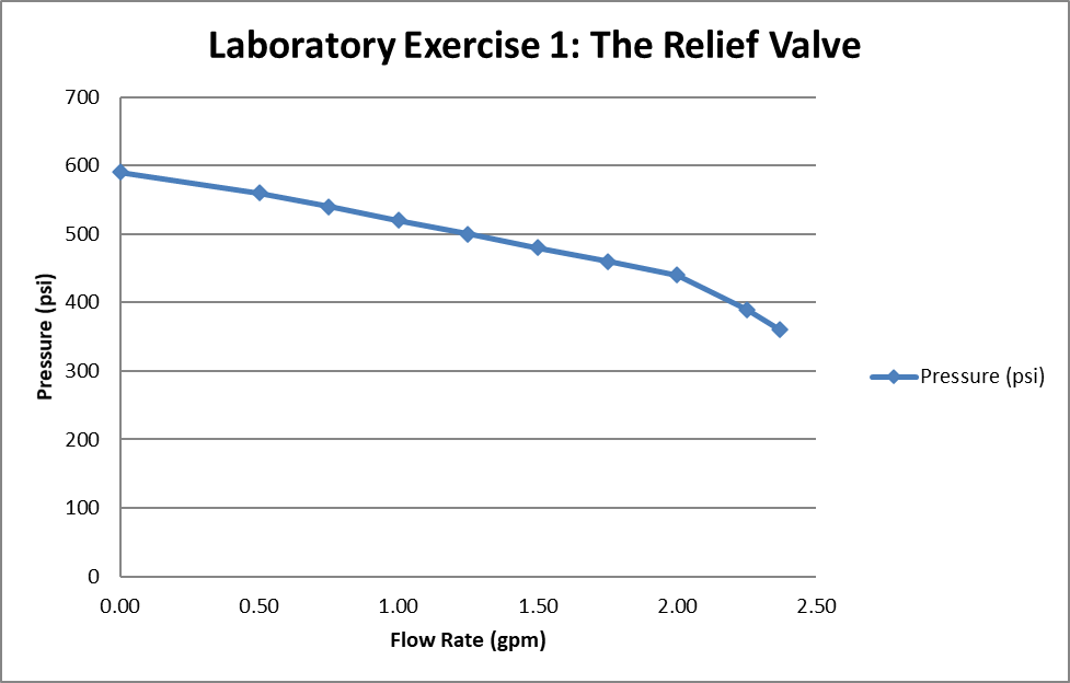
Observations:
My observation on this experiment would be that from 0.00 gpm to 2.00 gpm the relationship between the flow rate and pressure would be an inverse linear equations. From 2.00 gpm to 2.37 gpm the relationship between pressure and flow rate would also inverse linear equation but with a steeper slope.
Lab Findings:
My conclusion is that the relationship between flow rate and pressure is an inverse linear relationship. As flow rate increases the pressure will decrease.
Conclusion
In conclusion, pressure relief valves are vital components in hydraulic systems, ensuring safe and reliable operation under varying conditions. These valves are essential for regulating pressure and preventing system failures. However, their performance can be affected by instability issues, particularly in harsh environments. Understanding the different types of relief valves, such as direct-acting and pilot-operated, and the factors that contribute to their vibration and instability, is crucial for optimizing their function. Ongoing research and the development of robust fault diagnosis models are key to enhancing the reliability and efficiency of hydraulic systems, ultimately contributing to safer and more effective operations.

