Understanding Capacitance and Dielectrics
In physics, electric phenomena play a fundamental role, in shaping everything from electronics to modern technologies. Two essential concepts—capacitance and Dielectrics—serve as the foundation for understanding how these phenomena operate. Let’s delve into what capacitance and Dielectrics entail, the equations that define them, and their practical implications.
Capacitance: Storing Electrical Energy
Capacitance is a property of a system where two conductors hold opposite charges. By storing electrical energy, capacitors are critical components in nearly all electrical circuits. Let’s break down some of the essential equations and terms.
Defining Capacitance
Capacitance C is defined as the ratio of the charge Q stored on the conductors to the potential difference Vab between them:

Capacitance is measured in farads (F), where F = farad =Coulomb/volt = C/V = Coulomb per volt. The key point is that a capacitor’s capacitance is always positive, ensuring it can only add energy to a circuit. (Don’t confuse the capacitance C with the charge unit C = coulomb.)
Work and Energy in Capacitors
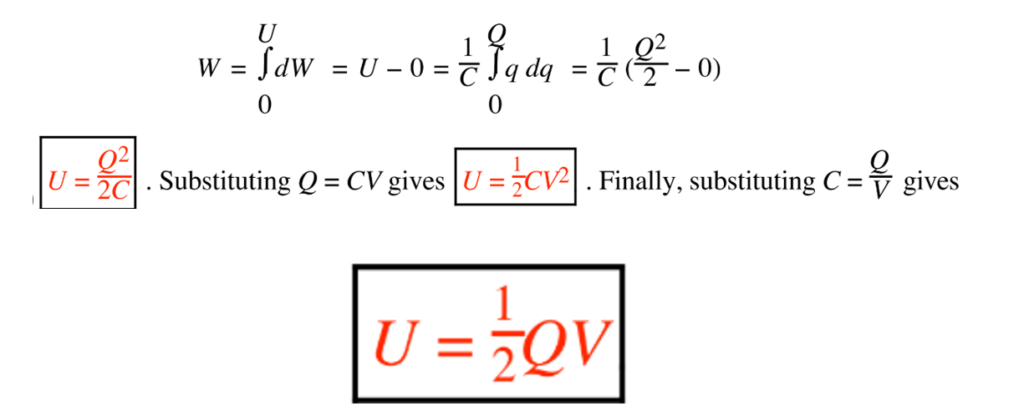
A capacitor is a circuit element that mainly provides capacitance. When a small charge dq is moved between the capacitor plates, the work dW done becomes stored as electric potential energy U. Integrating the work over the charge moved, we arrive at the potential energy stored in a capacitor:

V is short for the potential difference Va – Vb = Vab (in V). U is the electric potential energy (in J) stored in the capacitor’s electric field. This energy stored in the capacitor’s electric field becomes essential for powering various applications, from smartphones to electric cars (EVs).
Role of Dielectrics
Dielectrics are materials with very high electrical resistivity, making them excellent insulators. However, not all insulators qualify as good dielectrics. Beyond simply isolating components in AC circuits, dielectrics play a critical role due to their electric dipole properties. These dipoles, consisting of positive and negative charges separated by a distance, either exist naturally within the material or are induced in direct or alternating electric fields. This unique behavior is fundamental to understanding their characteristics and applications.
A dielectric can be placed between the plates of a capacitor to increase its capacitance. The dielectric strength Em is the maximum electric field magnitude the dielectric can withstand without breaking down and conducting. The dielectric constant K has no unit and is greater than or equal to one (K ≥ 1).

more charge is stored on the plates for the same voltage.
If we fill the entire space between the capacitor plates with a dielectric while keeping the charge Q constant, the potential difference and electric field strength will decrease to V=V0 /K and E=E0 /K respectively. Since capacitance is defined as C = Q/V the capacitance increases to KC0
Dielectric Properties of Various Materials at 300K
| Material | Dielectric Constant (at 10610^6 cycles) | Dielectric Strength (kV/mm) | Loss (tan δ) |
|---|---|---|---|
| Air | 1.0 | 3.0 | |
| Alumina | 8.8 | 1.6–6.3 | 0.0002–0.01 |
| Cellulose acetate | 3.5–5.5 | 9.8–11.8 | |
| Glass (soda-lime) | 7.0–7.6 | 1.2–5.9 | 0.004-.011 |
| Mica | 4.5–7.5 | 2.0–8.7 | 0.0015-.002 |
| Nylon | 3.0–3.5 | 18.5 | 0.03 |
| Phenol-formaldehyde resin (no filler) | 4.5–5.0 | 11.8–15.8 | 0.015-0.03 |
| Polyester resin | 3.1 | 17.1 | 0.023–0.052 |
| Polyethylene | 2.3 | 18.1 | 0.0005 |
| Polystyrene | 2.4–2.6 | 19.7–27.6 | 0.0001–0.0004 |
| Porcelain (high-voltage) | 6–7 | 9.8–15.7 | 0.003-0.02 |
| Pyrex glass | 500 | ||
| Rubber (butyl) | 2.3 | 23.6–35.4 | 0.06 |
| Silica thin films (gate oxide) | 3.8 | 700 | 0.0002 |
| Silicone molding compound (glass-filled) | 3.7 | 7.3 | 0.0017 |
| Steatite | 5.5–7.5 | 7.9–15.8 | 0.0002–0.004 |
| Styrene (shock-resistant) | 2.4–3.8 | 11.8–23.6 | 0.0004–0.02 |
| Titanates (Ba, Sr, Mg, Pb) | 15–12,000 | 2.0–11.8 | 0.0001–0.02 |
| Titanium dioxide | 14–110 | 3.9–8.3 | 0.0002–0.005 |
| Urea-formaldehyde | 6.4–6.9 | 11.8–15.8 | 0.028–0.032 |
| Vinyl chloride (unfilled) | 3.5-4.5 | 31.5–39.4 | 0.09–0.10 |
| Zircon porcelain | 8–9 | 9.8–13.8 | 0.0006–0.002 |
Why does E = E0/K?
The electric field E equals E0/K because of the interaction between the dielectric and the capacitor’s original electric field E0.
- Polarization of the Dielectric:
The free charges on the capacitor plates generate an applied electric field E0. When a dielectric is placed between the plates, this field exerts a torque on the electric dipoles within the dielectric material. These dipoles align with the field, creating induced bound charges on the dielectric surfaces. This alignment is called the polarization of the dielectric. - Opposing Electric Field:
The induced bound charges on the dielectric generate an electric field that opposes the original electric field E0. As a result, the net electric field inside the capacitor is reduced.

The degree to which the field is reduced depends on the material’s dielectric constant K, leading to the resultant electric field E = E0/K. This relationship reflects how the dielectric diminishes the overall field by opposing the initial applied field.
Dielectric Loss
Dielectric loss and breakdown are inherent limitations of dielectric materials. Dielectric breakdown leads to catastrophic failure, while dielectric loss can be managed through design. Dielectric loss occurs because real capacitors have resistive components that dissipate energy as Joule heat, reducing the ideal phase difference between current and voltage.
The measure of this loss, tan δ, represents the ratio of energy lost per cycle to the maximum stored energy. Analogous to mechanical systems, where energy dissipation occurs through internal friction or viscous flow, dielectric materials lose energy as dipoles fail to align perfectly with alternating electric fields. At high frequencies, polarization delays and molecular friction contribute to energy dissipation, ultimately converting it into heat through defect motion and diffusional processes.
Dielectric Breakdown
Dielectric breakdown occurs when a high electric field causes an insulator to fail irreversibly, often resulting in melted or vaporized material, holes, and craters. The breakdown field, measured in V/cm or kV/mm, indicates the material’s dielectric strength, similar to tensile strength in mechanics. Mechanisms of breakdown include impact ionization, where accelerated carriers ionize atoms, releasing more carriers and causing a rapid current increase, amplified by Joule heating that leads to thermal runaway. Proper design, such as shaping insulators with ribbed surfaces, helps mitigate breakdown by reducing surface conduction risks. This phenomenon is especially critical in microelectronics, where thin oxide layers are prone to failure under high voltage stress.

Permittivity:
We have been using the symbol ε0 without naming it: ε is the permittivity of a dielectric and ε0 is a special value of ε, the permittivity of a vacuum. The units of permittivity are C2/ Nm2 or F/m. The relation between ε and ε0 is ε = Kε0. In a vacuum, ε=ε0 and K=1. In air, ε is slightly greater than ε0 and K is
slightly greater than 1.
Gauss’s Law with Dielectrics:
For dielectrics, ∫E⋅dA=Qencl-free/ ε0K, modifying the electric field equations to include the dielectric’s effect. where Qencl-free is the total free (not bound) charge enclosed by the Gaussian surface, thus, if the dielectric(s) keep sufficient symmetry, we can take our previous results for E and Vab in a vacuum and simply replace ε0 with either ε or Kε0.

Parallel-plate capacitor
Structure and Assumptions:
A parallel-plate capacitor consists of two large, flat conducting plates separated by a small distance d.
The plate area A is much larger than the separation d, ensuring a uniform electric field between the plates, except near the edges.
Electric Field and Potential Difference:
The electric field between the plates is constant and given by E=Q/εA, where Q is the charge on the plates, A is the plate area, and ε is the permittivity.
The potential difference Vab between the plates is related to the electric field and separation by Vab=E⋅d
Capacitance:
The capacitance of a parallel-plate capacitor is given by C=ε/Ad, where ε=Kε0 for a dielectric-filled capacitor.
Adding a dielectric increases the capacitance by a factor of K, the dielectric constant.
Energy Density:
The energy density (electric potential energy per unit volume) of the electric field between the plates is:

This expression is valid for idealized cases without field fringing.
These relationships highlight the dependence of capacitance and energy storage on the geometry of the plates and the material between them.
Conclusion
In conclusion, understanding capacitance and dielectrics is essential for anyone exploring the principles of electrical and electronic systems. Capacitance, as a measure of a system’s ability to store energy, plays a pivotal role in powering modern devices. At the same time, dielectrics enhance this capability by increasing energy storage and improving efficiency.
However, the properties of dielectrics, such as dielectric loss and breakdown, also present challenges that must be addressed through thoughtful design and material selection. By mastering these concepts, engineers and scientists can innovate solutions that drive technological advancements in energy storage, communication systems, and microelectronics, laying the foundation for a more connected and efficient world.


