Conventional Powertrain Explained
Have you ever wondered how a conventional powertrain makes your car move? Today, we’re diving into the world of conventional powertrains, the beating heart of most vehicles on the road. In a conventional powertrain, an internal combustion engine (ICE), transforms the stored energy from gasoline or diesel fuel into kinetic energy within the engine. This energy is then transferred as torque through the transmission, driveshaft, and differential to the vehicle’s wheels, moving it forward. Strap in as we break down the complexities of internal combustion engine (ICE) based propulsion systems in a way that’s easy to understand.
What is a powertrain?
A powertrain are all the components that transfers power from a vehicle’s engine to its axle. A powertrain is used all types of vehicles, boats, or other types of construction machinery, designed to propel them forward. In a car, the powertrain includes the engine or motor and its internal components, such as the energy storage system (gas tank/ battery), transmission, and driveshaft.
ICE-based Propulsion Systems
The majority of powertrain systems in use today are based on ICE, which can be either spark ignition (SI) for gasoline or compression ignition (CI) for diesel engines. The electrification of road vehicles has led to an increase in the production of hybrid engines, which combine ICE and electrified powertrains, as well as fully electrified systems. Electrified systems can derive energy from various sources, including onboard generation, plug-in charging, or hydrogen fuel cells.
Components of a Conventional Powertrain
Let’s start with the basics. ICE-based propulsion systems are the most common type found in cars today. While electric and hybrid systems are gaining popularity, ICE still rules the roads. The ICE-based propulsion systems include the engine, transmission, propeller shaft (rear-wheel drive), differential with final drive, drive shafts, and wheels.

Each component plays a crucial role in getting your car from point A to point B. The engine is like the heart, pumping power through the transmission, which acts like a set of gears, adjusting the power to match your speed and load. The driveline and differential help transfer this power to the wheels, propelling you forward with each press of the gas pedal.
Rear Wheel Drive Explained
A Rear-Wheel Drive (RWD) vehicle is a type of vehicle where the engine’s power is transmitted to the rear wheels only. In RWD vehicles, the front wheels are responsible for steering, while the rear wheels are responsible for driving the vehicle forward.

This configuration offers several advantages, including better weight distribution, which can improve handling and traction, especially in high-performance vehicles. RWD vehicles are also known for their simplicity and durability, as the drivetrain components are relatively straightforward compared to more complex all-wheel drive or front-wheel drive systems. Overall, RWD vehicles offer a unique driving experience and are favored by enthusiasts for their handling characteristics and performance capabilities.
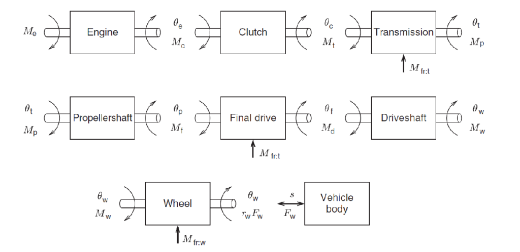
Vehicle Driveline for RWD
The following is a breakdown of how energy is transferred from the engine to the wheels in an RWD vehicle.

High-Level Modeling of a Conventional Powertrain
Picture this: power flows from the engine to the wheels, making your car move. Torque and horsepower are the key players here. Torque is the twisting force that gets you moving, while horsepower keeps you cruising down the highway. Understanding how these forces work together helps you appreciate the engineering behind your ride. The maximum (and minimum) engine torque 𝜏𝑒, max (min) is typically
described as a function of the engine speed 𝜔𝑒.

Internal Combustion Engine: The Heart of a Conventional Powertrain
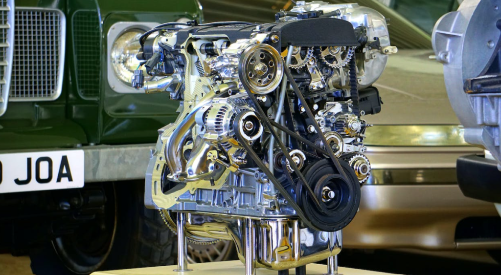
The engine comprises a stationary cylinder and a piston in motion. The expanding combustion gases exert pressure on the piston, causing it to move and rotate the crankshaft. This rotational motion is then transmitted to the vehicle’s wheels via a series of gears in the powertrain, propelling the vehicle forward. The four essential components required for an engine to run are spark, air, fuel, and compression.
Engine Efficiency
Engine efficiency is crucial in determining how effectively an internal combustion engine (ICE) converts fuel into usable energy. One key aspect is that the thermodynamic efficiency of ICEs largely hinges on the engine speed and torque. These factors influence how efficiently the engine converts fuel into power, impacting both performance and fuel economy. To assess fuel consumption, simplified formulations or 2D look-up tables are commonly used. These tools help engineers understand how different operating conditions affect fuel efficiency, allowing them to optimize engine performance for a balance of power and economy.

The more efficient your engine, the less fuel it burns. The BCFC map displays the engine efficiency calculated using a standard thermodynamic engine process simulation program. These calculations do not account for any mixture enrichment at high loads. As a result, the highest efficiencies are achieved under full load conditions. The map also illustrates the constant power curves and the estimated limits of maximum mean effective pressure.
Brake Specific Fuel Consumption (BSFC)
Brake Specific Fuel Consumption (BSFC) is a critical metric used to evaluate the efficiency of an engine in converting fuel into usable energy. It is essentially the measurement of how efficiently an engine combusts the fuel-air mixture and translates that energy into the rotational motion of the crankshaft, which ultimately propels the vehicle.

BSFC is typically expressed in units of grams per kilowatt-hour ([g/kW-hr]), providing a standardized measure of fuel efficiency across different engines and operating conditions. The fuel mass flow rate, a key component in calculating BSFC, is measured in grams per second ([g/s]), reflecting the amount of fuel consumed per unit time to sustain engine operation. Understanding and optimizing BSFC is crucial for improving overall engine performance and reducing fuel consumption.
Sample Problem
Using the engine data (engine speed, engine output torque, and engine fuel rate) in the file HW3Prob1.zip,
(i) Generate a brake-specific-fuel-consumption (BSFC) map using the equation discussed in Lecture 3.
(ii) Determine the optimal operating line (OOL) of the engine. The OOL is defined by a set of points
that have the lowest fuel consumption of those on constant-power curves.
(iii) Also, using the following gear ratios and the vehicle parameters in the file, generate a single figure
showing the maximum wheel force curve vs. vehicle speed at each gear ratio similar to the one
discussed in Lecture 3.
- gear ratios: {5.25, 3.03, 1.95, 1.46, 1.22, 1, 0.81, 0.67},
- final drive: 2.8,
- Vehicle mass: 1500 kg,
- air density: 1.2 kg/m3,
- Frontal area: 1.6 m2,
- Aerodynamic drag coefficient: 0.25.
- Tire radius: 0.32m

load(’engine_map_data.mat’)
[X1,Y1] = meshgrid(engine_rpm, engine_trq);
mf = Fuel_rate_2DLUT’;
Pe = (X1*2*pi/60).*Y1/1000;
BSFC = (3600*mf./Pe);
figure(’Name’, ’P1-i’)
plot(engine_rpm, Max_torque_1DLUT,’k’, ’LineWidth’,2.5, ’DisplayName’, ’Max Torque’); hold on;
contour(X1, Y1, BSFC, ’ShowText’, ’on’, ’Linewidth’,2, ’LevelStepMode’, ’manual’, ’LevelStep’,5,’DisplayName’,’BSFC’);
ylabel(’Engine Torque [Nm]’); colormap turbo
yyaxis right; contour(X1, Y1, Pe,10, ’LineColor’, [0.5, 0.5, 0.5],’DisplayName’,’Power’);
xlabel(’Engine RPM [rpm]’);ylabel(’Engine Power [kW]’);
Spd_engine = linspace(min(engine_rpm),max(engine_rpm),50);
P_values = linspace(1000, max(engine_rpm)/60*2*pi*max(engine_trq), 50);
for i = 1:length(P_values)
Trq_engine = P_values(i)./(Spd_engine*2*pi/60);
BSFC_temp=interp2(engine_rpm,engine_trq,BSFC,Spd_engine’,Trq_engine’);
[M,I(i)]=min(BSFC_temp);
OOL_trq(i)=Trq_engine(I(i));
end
OOL_spd = P_values./OOL_trq*60/2/pi;
MaxTorqueInterp = interp1(engine_rpm, Max_torque_1DLUT, OOL_spd,’cubic’);
rowsToreplace = (OOL_trq > MaxTorqueInterp);
OOL_trq(rowsToreplace) = MaxTorqueInterp(rowsToreplace);
yyaxis left;plot(OOL_spd, OOL_trq,’b+-’, ’LineWidth’, 3,’DisplayName’,’OOL’);
legend(’show’); yyaxis left; ylim([0,max(engine_trq)]);
title(’HW3 -P1: i & ii’, ’BSFC Plot and Optimal Operating Line’)
This creates a figure:
Gear Box
The gearbox is where the magic happens. It adjusts the speed and torque of the engine to match your driving conditions. Gearboxes play a crucial role in vehicles by transforming the mechanical power provided by a power source, such as an engine, at a certain speed (ω1) and torque (τ1) to a different speed (ω2) and torque (τ2) level. There are several types of gearboxes, each with its characteristics:
- Manual transmissions (MT) have a finite number of fixed gear ratios and are operated by the driver, who manually shifts gears using a gear stick and clutch pedal.
- Automatic transmissions (AT) also have a finite number of fixed gear ratios but feature a gear shift mechanism that automatically selects the appropriate gear based on the vehicle’s speed and load. ATs also include components such as hydraulic torque converters, automated clutches, and dual clutches (DCT) to facilitate smooth gear changes.
- Continuously variable transmissions (CVT), on the other hand, can provide any desired gear ratio within their limits, offering a seamless and efficient driving experience.

Why Conventional Powertrains Need a Transmission
Why do we need a transmission? Well, without it, your engine would either be screaming at high speeds or struggling at low speeds. The transmission helps your engine stay in its sweet spot, making sure you have power when you need it. Transmissions play a crucial role in matching the engine’s power output with the various speed and load conditions encountered during vehicle operation. The selection of gear ratios in a transmission is a complex optimization problem that aims to achieve the best balance between towing capability, top speed, and fuel economy.

In general, the largest gear ratio is chosen to meet towing requirements, providing the necessary torque for pulling heavy loads. On the other hand, the smallest gear ratio is selected either to reach the top-speed limit or to maximize fuel economy, ensuring efficient operation at higher speeds or during cruising. The transmission’s ability to adjust gear ratios allows the engine to operate at its optimal efficiency across a range of driving conditions, making it a critical component in modern vehicles.
Gear Shifting Map
The gear shifting map is a critical tool in modern vehicle design, focusing on achieving instantaneous optimization of Brake Specific Fuel Consumption (BSFC). The underlying assumption is that human drivers can modulate the throttle to adjust power output if needed, allowing the transmission to focus on maximizing fuel efficiency.
The procedure involves calculating the BSFC for different engine speeds and loads and selecting the gear that allows the engine to operate at its most fuel-efficient speed. This approach to gear selection is part of the broader field of vehicle energy management, which aims to maximize fuel efficiency and performance while minimizing emissions. The gear-shifting map is a key component of this strategy, ensuring that the vehicle operates as efficiently as possible under various driving conditions.

The gear-shifting map is like a cheat sheet for your gearbox. It tells the transmission when to shift gears based on engine speed and load. By following the map, your car can optimize performance and fuel efficiency, giving you the best of both worlds.
What is the difference between a powertrain and a transmission?
Powertrain refers to all the components responsible for propelling the vehicle, comprising the engine, transmission, and driveline components (differentials, axle shafts, and joints, which we’ll detail later). Drivetrain, on the other hand, encompasses the powertrain components excluding the engine, so it includes the transmission and the driveline components.

Torque Converter
For automatic transmissions, there’s the torque converter. A torque converter is a hydrodynamic fluid coupling device that transfers the rotating power from an engine to a transmission input shaft. It’s like a hydraulic clutch that allows your engine to keep running while your car is stopped. It’s a nifty little device that makes driving an automatic feel smooth and effortless.

Torque Converter Model
The torque converter model is essential for understanding the performance of automatic transmissions. It is based on tabulated characteristics that relate the torque ratio and capacity factor to the speed ratio of the converter. The speed ratio (SR) is defined as the ratio of the turbine speed (ωt) to the pump speed (ωp), while the torque ratio (TR) is the ratio of the turbine torque (τt) to the pump torque (τp). The capacity factor (K) is calculated as the pump speed (ωp) divided by the square root of the torque (τ). These parameters help engineers design and optimize torque converters for specific applications, ensuring that they operate efficiently and effectively under various operating conditions.

Conclusion
And there you have it! A crash course in conventional powertrains. Next time you hit the road, take a moment to appreciate the engineering marvel that propels you forward. Understanding powertrains not only makes you a better driver but also gives you a glimpse into the world of automotive engineering. Until next time, drive safe and stay curious!

