How Vehicle Mass Impacts Brake System Design
The race to reduce vehicle mass has become one of the defining engineering challenges of today’s automotive industry. Driven by historically aggressive fuel economy regulations and the push for greater efficiency, manufacturers are scrutinizing every subsystem in the vehicle for weight savings, including brake systems. Although the mass of the braking system is closely tied to its performance and quality, it has not escaped the spotlight in the pursuit of lightweighting.
However, optimizing brake system mass is far from straightforward. As with many modern automotive systems, the brake system is highly integrated and constrained by a complex web of performance targets, durability requirements, and packaging limitations. Finding opportunities to reduce weight without compromising braking performance, thermal capacity, or NVH (noise, vibration, harshness) quality requires a deep understanding of the intricate relationships between brake components and the broader vehicle architecture.
How does increased engine power affect the brake system mass? What role do tire and wheel size play? What is the weight cost of extended pad life or NVH enhancements? These are just a few of the fundamental questions engineers must answer. To clarify these trade-offs, researchers developed an integrated model that links brake performance with mass prediction, leveraging benchmarking data and regression analysis to expose key mass drivers and enable system-level optimization.
The Mass-Brake System Link: Not Just Intuitive, But Quantifiable
It’s widely understood that vehicle mass and brake system mass are closely linked; when vehicle weight goes down, brake system mass can often be reduced in tandem. Numerous studies have attempted to quantify this relationship, often using what’s known as a mass decompounding coefficient. This coefficient represents the amount of subsystem mass that can be saved for every kilogram of vehicle mass reduction.
For example, research by Caterina Bjelkengren using regression analysis estimated a coefficient of 0.032 for combined brake and steering systems, meaning a 100 kg reduction in vehicle mass could yield a 3.2 kg reduction in those subsystems. When isolating the brake system, this figure adjusts to approximately 0.024. Other sources vary: Malen reported a higher coefficient of 0.24, while internal GM studies have shown values ranging from 0.038 in earlier work to 0.01 more recently. These variations likely stem from differences in datasets and statistical methodologies used.
To validate these “top-down” estimates, the study referenced here employed a “bottom-up” approach, building a brake system model from the component level, driven by thermal performance criteria. As vehicle mass increases, so must the system’s thermal capacity and cooling ability to maintain operating temperatures within a safe range during repetitive braking events.
In the analysis, the vehicle’s gross (laden) mass was varied between 1500 kg and 2500 kg for a typical front-wheel-drive setup. Brake force distribution remained constant, while the front rotor’s thermal mass was adjusted to meet a defined equilibrium temperature limit during a repeated braking cycle (from 64 to 24 kph with 20-second intervals). The rear rotor geometry was scaled accordingly for balance, and the size of the brake-apply system was also adjusted based on vehicle mass. The results are plotted in Figure 1 below:
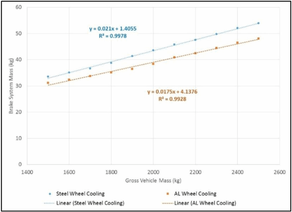
Mass for Steel and Aluminum Wheel Cooling
The results showed a clear relationship: 0.021 kg of brake system mass per 1 kg of vehicle mass. This aligns well with previous estimates, demonstrating that even a simple thermal sizing requirement can produce a reliable mass scaling relationship. Additionally, the type of wheel significantly influenced brake system mass. Switching from steel to aluminum wheels (while maintaining equivalent cooling performance) enabled 2.4 to 6 kg of brake mass savings, highlighting how mass reductions in one area can enable further savings in another.
It’s worth noting that in practice, brake mass isn’t always added when thermal demand increases. Sometimes, operating temperatures can rise (still within acceptable limits), impacting brake pad life, noise performance, and overall NVH characteristics.
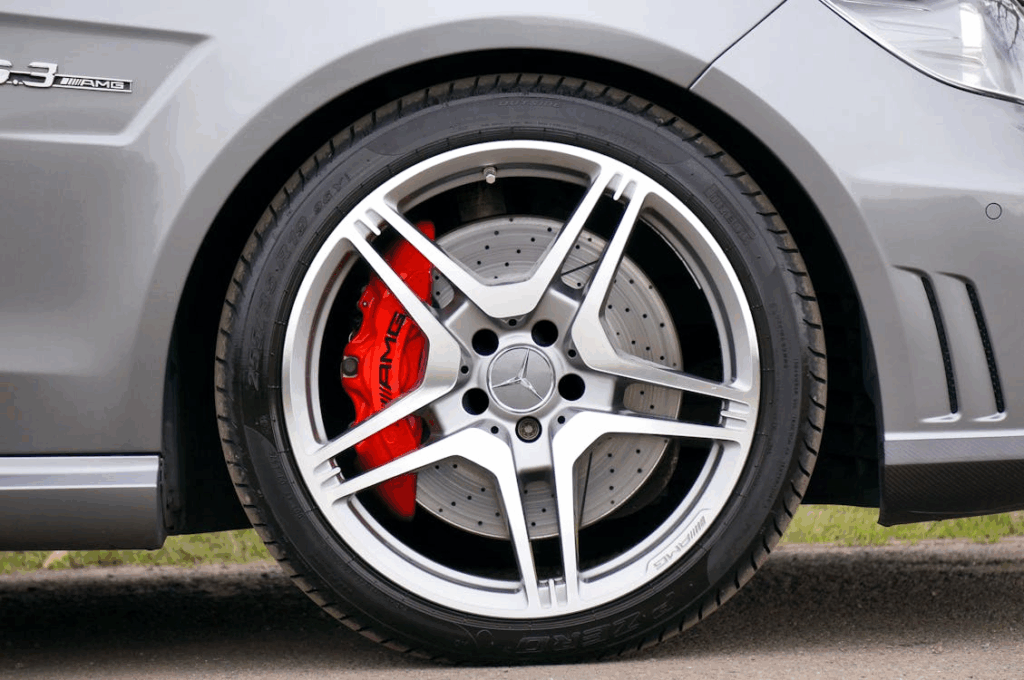
Wheel and Tire Size Amplify the Effect
It’s well understood that as a vehicle’s tire and wheel size increases, more precisely, as the static loaded radius (the effective distance from the wheel center to the ground) grows, the braking system must generate more torque/ braking forces to achieve the same level of tractive force at the road surface. A larger radius increases the moment arm, requiring greater brake torque to counter the same driving force.

Mass
Engineers often work within a hydraulic pressure limit to manage this, which becomes a key constraint when designing the brake system. There are three primary reasons for capping brake pressure:
- To limit the size and complexity of the brake-apply system,
- To ensure smooth integration with vehicle chassis controls (like ABS, traction control, and stability systems), and
- To maintain pressure within a range that supports long-term component durability.
A commonly accepted industry benchmark is achieving 1.0g of deceleration using no more than 100 bar of hydraulic pressure. In a compact sedan, adhering to this requirement and assuming a typical brake pad friction coefficient of 0.32 necessitates increasing the caliper piston size as the wheel radius grows. This upscaling of piston area ensures adequate torque output without exceeding the pressure limit.
However, increasing the caliper piston size creates a cascading effect:
- The master cylinder must also be upsized to maintain acceptable pedal travel and stroke.
- The brake booster and apply system output must grow to preserve proper runout and pedal feel.
- And to maintain brake balance, rear caliper piston areas must also increase proportionally.
The study data (referenced in Figure 2) reveals a clear trend: brake system mass increases by roughly 195 grams for every 10 mm increase in static loaded radius. The front caliper piston size also scales accordingly, growing from about 57 mm at a 290 mm tire radius to 62 mm (or a dual 44 mm equivalent) at 370 mm.
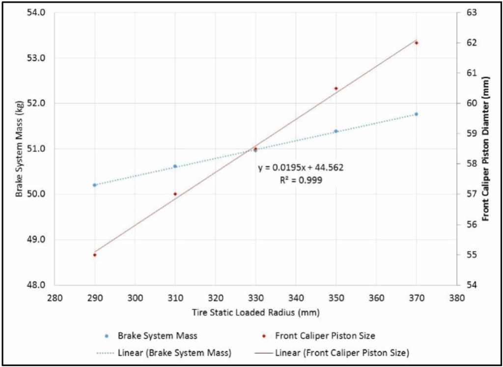
Radius (hydraulic pressure limits drive mass)
However, the effect on component packaging is more impactful than the mass increase. Larger pistons often require larger calipers and pads, which may not fit within the original wheel envelope. This can ultimately drive the need for larger brake rotors and wheels, further compounding the mass penalty.
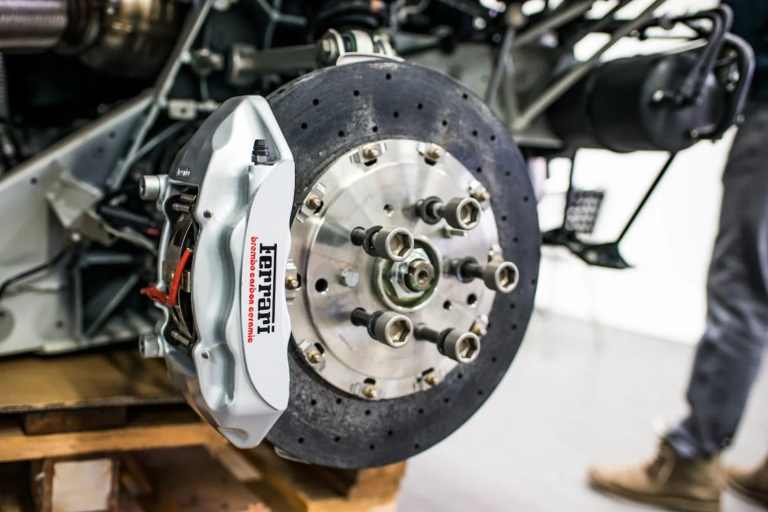
Why do sports cars have bigger brakes?
It’s long been understood that as a vehicle’s engine power increases, its brake system must also be upgraded to handle the added performance. This is the reason why sports cars need larger brakes. Brake sizing and cooling capabilities must align with the vehicle’s acceleration potential to ensure consistent and safe deceleration. This relationship is often validated using fade tests, which stress the brake system to evaluate its ability to manage heat under repeated high-speed stops.
With larger brakes, drivers can delay braking, maintain better control through corners, and ultimately complete laps more quickly. Bigger rotors and pads increase friction and a greater stopping force, resulting in shorter braking distances. Additionally, their improved ability to dissipate heat makes them especially valuable in high-performance track conditions where thermal management is critical.
What are the AMS2 and AMS3 brake tests, and why are they important in evaluating brake system performance?
One of the most widely accepted testing standards comes from the German publication Auto Motor und Sport, whose AMS2 and AMS3 tests have become benchmarks in the automotive industry. The AMS2 test involves an initial cold stop from 100 km/h, followed by 10 full-throttle accelerations and maximum-effort stops from 100 km/h, back-to-back. Brake systems that perform well in this test show minimal loss in deceleration capability; essentially, their fade resistance is strong.
A more aggressive procedure, AMS3, raises the bar. It includes nine cycles of wide-open throttle acceleration from 70 km/h to 80% of the vehicle’s top speed, followed by moderate braking down to 70 km/h. A final 10th stop from high-speed tests the system under maximum thermal stress. These tests challenge the brakes not just on raw stopping power but also on thermal endurance, with peak rotor temperature being a critical performance criterion.
In the study, a compact rear-wheel-drive sport sedan was analyzed. Engine output was varied from 150 hp to 500 hp for AMS2, and 200 hp to 550 hp for AMS3. The brake rotors were sized to meet both a general thermal equilibrium limit (from previous sections) and a stricter, scenario-specific AMS fade temperature threshold. Figure 3 below shows the results for the AMS2 simulation. Two vehicle masses were analyzed (a baseline, design intent mass, and a case of 200 kg heavier).
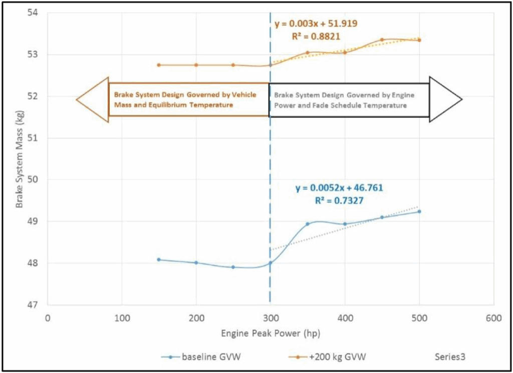
Compact RWD Sedan Meeting “AMS2” Temperature Limits
The AMS2 results showed that up to around 300 hp, the brake system sizing was driven by the equilibrium temperature requirement. Beyond this point, engine power began to significantly affect brake mass, as the reduced cooling time between acceleration runs caused rotor temperatures to rise. To manage this, larger rotors, providing greater thermal storage capacity, were needed. Once the system was thermally balanced for the vehicle mass, further increases in engine power placed only a moderate additional demand on the brakes. The relationship here can be approximated as 0.3 kg of brake system mass per 100 hp above that threshold.
How does the AMS3 test impact brake system design compared to AMS2?
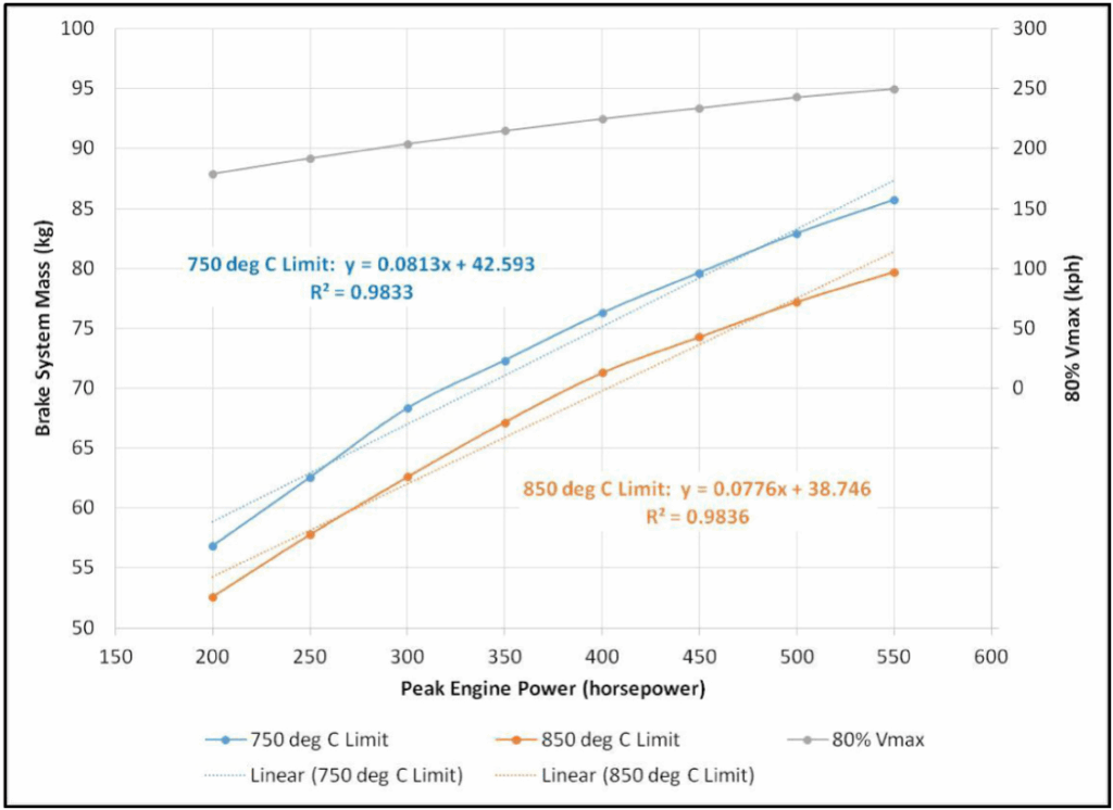
In contrast, the AMS3 test was far more demanding. Higher speeds and longer acceleration cycles placed greater thermal stress on the system. Brake system mass increased more sharply with engine power when maintaining fixed temperature limits,—750°C and 850°C were analyzed as design thresholds. Figure 4 below shows the brake system mass versus peak engine power for the same compact sport sedan.
vs. Peak Engine Power for Compact RWD Sedan Meeting “AMS3”
Temperature Limits
Several key relationships emerged from the AMS3 data:
- The brake system mass increased by approximately 8 kg per 100 hp, for both temperature limits.
- For every 100°C increase in the allowed rotor temperature, brake system mass could be reduced by about 4 kg, though this trend is non-linear and limited to the test’s temperature range.
- Meeting the stricter 750°C limit required the brake system mass to rise from 7 kg at 200 hp to over 28 kg at 500 hp.
These results emphasize that engine power and thermal constraints are deeply intertwined in brake system design. In high-performance vehicles, managing fade resistance and maintaining thermal limits becomes increasingly difficult—and costly in terms of mass—as engine output climbs.
Vehicle Mass Distribution and Brake System Mass
Vehicle mass distribution, and related factors such as center of gravity height and wheelbase, which influence weight transfer during braking, can significantly affect brake system mass through multiple mechanisms. To explore this, a case study was conducted using a mid-sized vehicle with a gross vehicle weight (GVW) of 2100 kg, where the brake system was optimized to assess sensitivity to static mass distribution. The optimization was performed under three primary constraints:
- Maintaining front and rear brake thermal equilibrium temperatures below a proprietary threshold,
- Setting the brake force distribution such that the “z-critical” value (the deceleration rate at which braking is balanced front to rear) equals 0.7g, and
- Ensuring front brake pressure remains below 100 bar to achieve 1.0g deceleration in the lightly loaded vehicle (LLVW) condition.
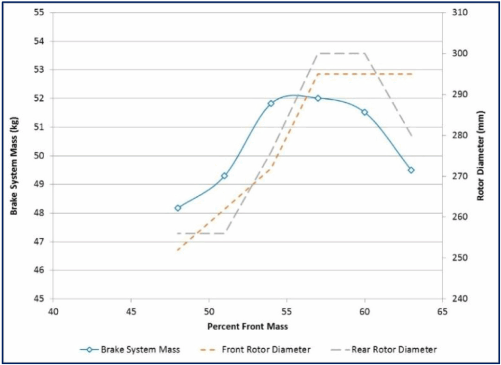
To simplify the analysis, the front caliper piston diameter was fixed at 1×60 mm. Figure 6 shows the results:
Distribution
The results revealed a nonlinear relationship between brake system mass and static front-to-rear mass distribution. A distinct peak in brake system mass was observed in the 52% to 60% front-biased range, with overall mass decreasing outside of this zone. Several factors contributed to this behavior:
- Highly front-biased vehicles require smaller rear brake components to maintain proper brake balance. Since the front brakes handle more of the braking load, and front brake sizing tends to be more mass-efficient than rear, total brake system mass decreases.
- As mass distribution becomes less front-heavy, the rear brakes must be upsized to maintain both force balance and thermal performance. However, front brakes still need to retain their sizing to keep pressure within limits, causing total brake system mass to increase.
- At around 54% front mass, rear brake thermal limits can no longer be met with solid rotors and standard hydraulics, requiring a switch to vented rear discs. While vented rotors can reduce diameter, they are heavier, adding to the total system mass. Interestingly, this switch results in rear brake temperatures dropping well below the thermal limit, indicating potential overcapacity.
- As the vehicle approaches a neutral weight distribution (around 50/50), the front brake load decreases, allowing both front and rear rotor sizes to be reduced. Since thermal and force balance can still be maintained, the brake system mass declines.
- At less than 50% front bias, the rear piston size must be increased to maintain proper brake balance. This pushes the rear system up to its thermal capacity limit, causing rear rotor sizing to once again be governed by the thermal specification.
In summary, mass distribution plays a complex and nuanced role in brake system sizing, with system mass highly dependent on how brake performance targets are defined. Even small changes in mass distribution can cause significant shifts in the optimal design of brake components, particularly when balancing thermal and hydraulic constraints.
The Effect of Brake Rotor Cooling on Mass and Fuel Economy
While not always obvious at first glance, there is an important, though somewhat indirect, relationship between brake cooling and vehicle mass. It’s well understood that enhancing brake cooling, typically by channeling more airflow to the brake rotor’s convective surfaces, can help reduce the size (and therefore mass) of brake components. However, brake assemblies are inherently aerodynamically inefficient, and components used to direct airflow (like ducts, deflectors, ramps, and open wheel designs) can increase aerodynamic drag, negatively impacting fuel economy.
For example, research by Wäschle found that using open wheels instead of closed ones increases the vehicle’s drag coefficient by about 15 counts (0.015 Cd), while GM internal data suggests this change can improve brake cooling by 15–20%. Similarly, CFD simulations by Jerhamre and Bergström showed that while an airdam in front of the wheels reduced drag by 7 counts, it decreased brake cooling by 4%. Another study by D’Hooge et al. found that reducing wheel vent area could drop drag by 22 counts (0.022 Cd)—further reinforcing this trade-off between cooling and aerodynamics.
This interplay presents a classic optimization challenge: is it better to accept more drag to enable lighter, better-cooled brakes, or to reduce drag and accept heavier, more thermally robust components? To explore this question, a case study was conducted using a compact sedan and a GM proprietary vehicle model to analyze fuel economy impacts due to changes in aerodynamic drag and brake system mass.
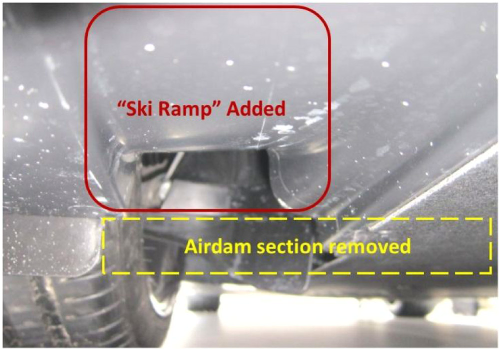
Improve Front Brake Rotor Cooling (Competitive benchmark vehicle
shown)
The study consisted of three steps:
- Brake Cooling Improvement with Aero Penalty:
A “ski-ramp” style airflow guide was virtually added just inside the front wheels to improve rotor cooling. A 5% brake cooling improvement was assumed, based on benchmarks and prior research. This change led to a reduction in brake system mass from 41.99 kg to 40.31 kg, a savings of 1.68 kg. However, the modified brake rotor size would fall into a non-standard “half wheel envelope” size, not ideal for packaging, and might necessitate a larger wheel, which could trigger further mass and cost implications. - Aerodynamic Drag Impact on Fuel Economy:
The airflow guide introduced an 8-count (0.008 Cd) increase in drag, resulting in a calculated fuel economy penalty of 0.18 mpg (composite). This translates to a sensitivity of 0.023 mpg lost per count of drag, and 0.045 mpg gained per 1% improvement in brake cooling. - Mass Offset Required to Compensate for Aero Losses:
To offset the 0.18 mpg fuel economy loss from increased drag, the vehicle would need to shed approximately 20.9 kg of mass elsewhere. This indicates a fuel economy-to-mass sensitivity of 116 kg per mpg, or about 0.008 mpg per kg of mass reduction.
Conclusion: A System-Level Optimization Challenge
The relationship between vehicle mass and brake system design is complex, multi-dimensional, and central to achieving a balanced vehicle architecture. As this article has shown, increasing vehicle mass influences not just the size of rotors and calipers but also the thermal, hydraulic, and packaging requirements of the entire braking system. From brake force balance and thermal limits to pedal feel and fade resistance, every aspect of brake performance must be scaled and optimized in parallel with changes in vehicle weight and layout.
Moreover, the interplay between mass reduction, brake cooling, and aerodynamic drag presents a significant design challenge, one that calls for careful system-level optimization. While lighter brakes can support mass and performance goals, they often require improved cooling, which can come at the expense of fuel efficiency due to increased drag. As vehicle platforms evolve and priorities shift toward electrification, lower drag, and reduced engine vacuum, the pressure on brake systems to perform with minimal weight and maximum efficiency will only increase.
Ultimately, understanding and quantifying how mass influences braking allows engineers to make more informed, data-driven decisions. By leveraging integrated modeling tools and embracing a holistic approach to system design, it’s possible to strike the right balance between safety, performance, mass, and efficiency, pushing the boundaries of what’s achievable in modern vehicle engineering.