The Magic of Cascade and Bandpass Filters
Hey there, tech enthusiasts! Today, we’re diving into the fascinating world of electronic filters, where signals go in one end and emerge transformed on the other. Buckle up as we embark on a journey through cascades, resonances, and the magical realm of bandpass filters!
What is a cascade filter?
Picture this: you have a signal that needs some tweaking. Maybe it’s too noisy, or you want to extract specific frequencies. This is where cascade filters come to the rescue. Imagine a team of experts, each with their unique skillset, working together to solve a complex problem. Cascade filters do something similar, but with electrical components!

At its core, a cascading (or hierarchical) filters is a combination of multiple filters connected one after the other. Each filter in the cascade does its bit to modify the signal, and when their powers combine, you get a customized output.
The Marvel of Cascaded Two-Port Networks
Now, let’s zoom in a bit. Cascaded two-port networks are the building blocks of cascade filters. When we link two ports in a cascade arrangement, we simply multiply their separate transmission parameters to derive the overall transmission parameters of the cascade connection (see equations below). By chaining them together, you can fine-tune your signal until it reaches the desired form.

What is series resonance?
let’s talk resonance! Series resonance is a resonance condition found in series circuits, where the current reaches its peak for a specific voltage value. Within series resonance, the current achieves its highest point at the resonant frequency. The current curve during series resonance ascends to its pinnacle at the resonance point and subsequently diminishes as the resonance point is surpassed

Imagine pushing someone on a swing. If you time your pushes just right, the swing goes higher and higher. In the world of electronics, a series resonant circuit does something similar. It’s like hitting the sweet spot in a game – the circuit responds most strongly to a particular frequency, amplifying it.
The series resonant circuit is like a cozy hammock swaying with the wind – it resonates when the frequency is just right. It’s a special arrangement of components that creates an electrical sweet spot.
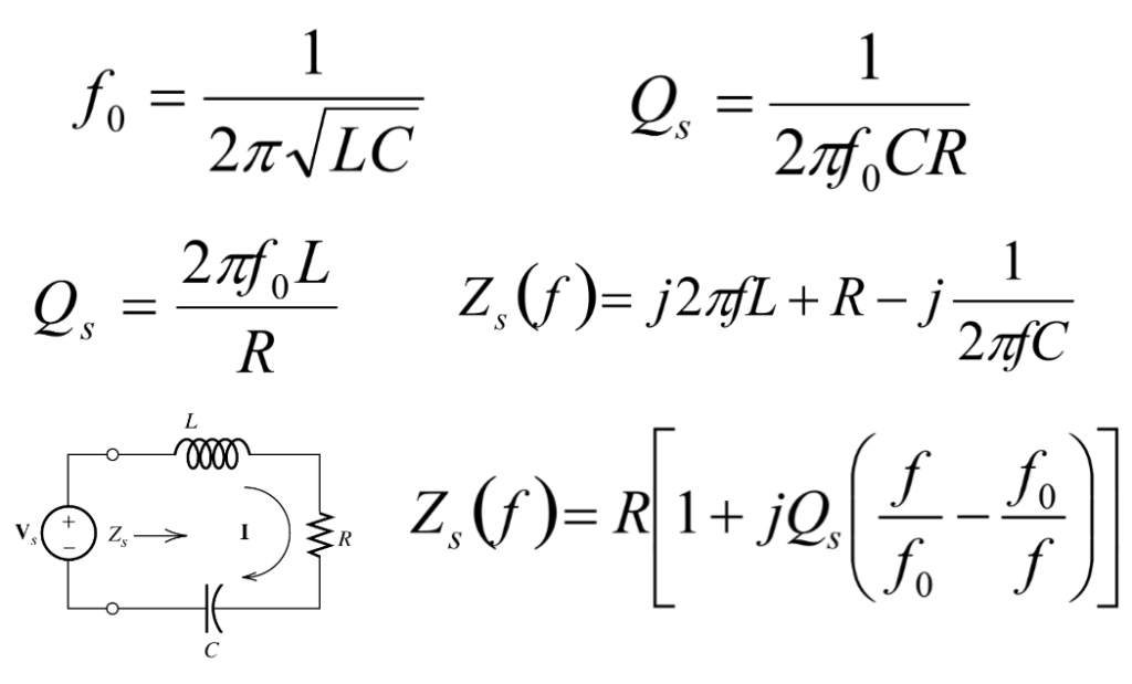
What is the formula for series resonant circuit?
The formulas below are applicable to series resonant circuits, and also parallel resonant circuits if the resistance is in series with the inductor. In the equations below C = Capacitive reactance at resonance, L = Inductive reactance at resonance and R = Series resistance.

Output/Input Dance of the Resonant Circuit
When a signal dances its way into a series resonant circuit at its favorite frequency, something enchanting happens. The circuit starts resonating – the amplitude of the signal grows stronger. It’s like catching the perfect wave while surfing. But remember, if you hit the wrong frequency, it’s like singing off-key at a concert – things might not go so well.

Series Resonance Steps into the Spotlight as a Band-pass Filter
Now, here’s where the series resonant circuit shows its versatility – it can moonlight as a bandpass filter. A band-pass filter works to screen out frequencies that are either too low or high, only allowing frequencies within a certain range to pass. Band-pass filters can be made by cascading a low-pass filter on the end of a high-pass filter, or vice versa. A bandpass filter is like a VIP section at a concert. It lets only a specific range of frequencies through while blocking out the rest.

How to design RLC circuit into a band pass filter?
With some algebraic manipulation, you obtain the transfer function of a band-pass filter. Thus allowing you to combine the resonance phenomenon with some clever circuitry, you can create a filter that lets a specific range of frequencies pass through. The RLC circuits shown below act as two-pole band-pass filters.

let’s dive into how a bandpass filter works!
Imagine you’re at a music concert, and you want to hear the lead singer’s voice clearly while blocking out the loud background noise and the bass-heavy beats. A bandpass filter in the world of electronics serves a similar purpose – it allows a specific range of frequencies to pass through while attenuating (weakening) frequencies outside of that range.
A bandpass filter is like a gatekeeper for frequencies. It’s designed to let only a certain “band” of frequencies through, hence the name “bandpass.” This is incredibly useful in various applications, such as audio processing, radio communication, and signal analysis.
Sample Problem

Applications:
- Audio Equalization: Bandpass filters are used in audio systems to emphasize or reduce specific frequency ranges, enhancing the quality of sound.
- Radio Communication: In radio systems, bandpass filters help isolate the desired frequency range, allowing clear reception while rejecting unwanted interference.
- Signal Analysis: Bandpass filters are essential in analyzing specific components of a complex signal, such as isolating certain frequencies in scientific experiments or research.

In a nutshell, a bandpass filter is like a frequency gate, allowing only a chosen range of frequencies to enter while keeping the rest out. It’s a tool that helps engineers and scientists tailor signals to meet specific requirements, much like how we fine-tune our senses to focus on particular aspects of the world around us.
In Conclusion
So there you have it, fellow tech explorers! We’ve ventured through the enchanting world of cascade filters, discovered the magic of series resonance, and witnessed its transformation into a bandpass filter superhero. Just like a DJ remixing a song to perfection, electronic filters remix signals to suit our needs. Whether it’s cleaning up audio, fine-tuning radio signals, or unleashing the power of resonance, these concepts weave together to create the symphony of modern technology. Keep tinkering, keep experimenting, and keep riding those resonant waves


