SAE International – Driver Hand Control Reach (SAE J287)
RATIONALE
This revision reduces the complexity of this practice by simplifying the General Package Factor (G) equation, clarifying conditions for using restrained and unrestrained reach tables, removing English unit tables, clarifying the G value boundaries between each reach table, describing in more detail how to interpret when a control is considered within reach, and limiting application of the practice to Class A vehicles.
The substantial simplification of the General Package Factor (G) equation (from 7 vehicle dimensions to 2) occurred as a result of a statistical investigation begun in 1997 by members of the SAE HADD committee.
A stepwise regression analysis was conducted on a data set of 81 vehicles spanning model years 1997 – 2005. The H30 dimensions were typical of passenger cars and light trucks, ranging from 188 mm to 374 mm. Heavy truck packaging data were not available to include in the analysis. Most of the vehicles in the dataset had reach zones identified by reach tables 4, 7, 10 in this document. It was determined for each vehicle that a significantly similar G value could be obtained from only two package variables, H30 and H17. The H17 dimension was found to be the best predictor for cars, while H30 was the best predictor for trucks and vans and for all vehicle types combined. The output of this simplified equation (Figure 3) fit the G values from the original equation with an R2 of 0.96, while the same reach table was selected for 93% of the vehicles. Based on this result, the committee adopted the simplified equation for G.
SCOPE
This recommended practice describes boundaries of hand control locations that can be reached by a percentage of different driver populations in passenger cars, multi-purpose passenger vehicles, and light trucks (Class A vehicles). This practice is not applicable to heavy trucks (Class B vehicles).
1.1 Introduction
The description of driver hand control reach envelopes was developed using data acquired from test subjects performing reach tasks in test fixtures simulating a range of actual vehicle configurations [Hammond and Roe, 1972; Hammond, et al, 1975]. The test subjects included equal numbers of men and women selected to represent the (United States) driving population on the basis of stature and age, and were tested both with and without an upper torso three-point restraint (the torso restraint was a diagonal non-extending shoulder strap attached separately to the lap belt; it was not a continuous loop system). The envelopes constructed using the non-extending shoulder and lap belt are meant to define a restrained hand reach, and the envelopes constructed using the lap belt only describe an unrestrained hand reach. The hand reach envelopes are three-dimensional surfaces described in table form and can be referenced to a particular vehicle seating configuration as described in Sections 5 and 6. The tables contained in this practice describe the boundaries to which at least 95% of US drivers can reach.
REFERENCES
2.1 Applicable Publications
The following publications form a part of the specification to the extent specified herein. Unless otherwise indicated, the latest revision of SAE publications shall apply.
2.1.1 SAE Publications
Available from SAE, 400 Commonwealth Drive, Warrendale, PA 15096-0001, Tel: 877-606-7323 (inside USA and Canada) or 724-776-4970 (outside USA), www.sae.org.
SAE J826 Devices for Use in Defining and Measuring Vehicle Seating Accommodation
SAE J1100 Motor Vehicle Dimensions
D. Hammond and R. Roe, “SAE Controls Reach Study.” Paper 720199 presented at SAE Automotive Engineering Congress and Exposition, Detroit, January 1972.
D. Hammond, D. Maurer, and L. Razgunas, “Controls Reach—The Hand Reach of Drivers.” Paper 750357 presented at SAE Automotive Congress and Exposition, Detroit, February 1975.
R. W. Roe, “Reach to Other Types of Controls.” Minutes of meeting of Design Devices Subcommittee, SAE Human Factors Engineering Committee, April 18, 1972.
2.2 Related Publications
The following publications are provided for information purposes only and are not a required part of this document.
2.2.1 SAE Publications
Available from SAE, 400 Commonwealth Drive, Warrendale, PA 15096-0001, Tel: 877-606-7323 (inside USA and Canada) or 724-776-4970 (outside USA), www.sae.org.
SAE J182 Motor Vehicle Fiducial Marks
SAE J941 Motor Vehicle Drivers’ Eye Locations
SAE J1052 Motor Vehicle Driver and Passenger Head Position
SAE J1516 Accommodation Tool Reference Point
DEFINITIONS
3.1 SAE J1100 Definitions
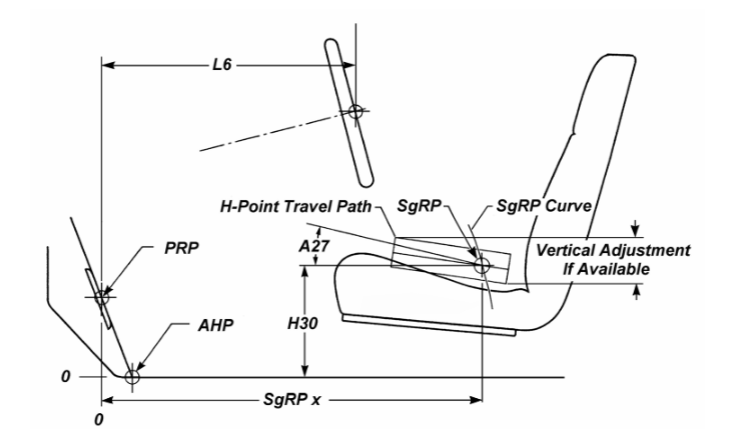
Accelerator Heel Point (AHP)
H-point
Actual H-point
Centerline of Occupant (C/LO, at Y-coordinate of SgRP)
Seating Reference Point (SgRP)
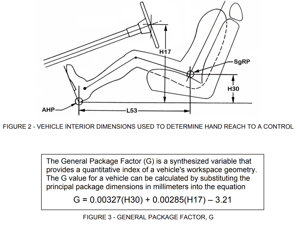
H17, Steering Wheel Center to AHP, z
H30, SgRP to AHP, z – Front
L53, SgRP to AHP, x – Front
Whenever H30 and L53 are used in this document, they apply to the driver seating position. The suffix “-1”, which is used in SAE J1100 to designate the front seating row, is herein omitted from the dimension.
3.2 Driver Hand Reach Capability
Maximum reach capability of 95% of drivers in a simulated driving situation with the non-reaching hand on the steering wheel and the right foot on the accelerator pedal.
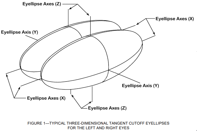
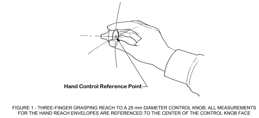
3.3 Basic Reach Task
Hand reach to a forward mounted control with the control held in a three-finger grasp. See Figure 1.
3.4 Hand Reach Envelope
Geometric description of the hand reach capability for a specified proportion of a driver population and type of torso restraint system. The contour of the hand reach envelope refers to the geometric center of the control knob face. If the control knob face is at, or rearward of, the contour, it is estimated that at least the specified proportion of the indicated driver population can reach and operate the control [Hammond and Roe, 1972].
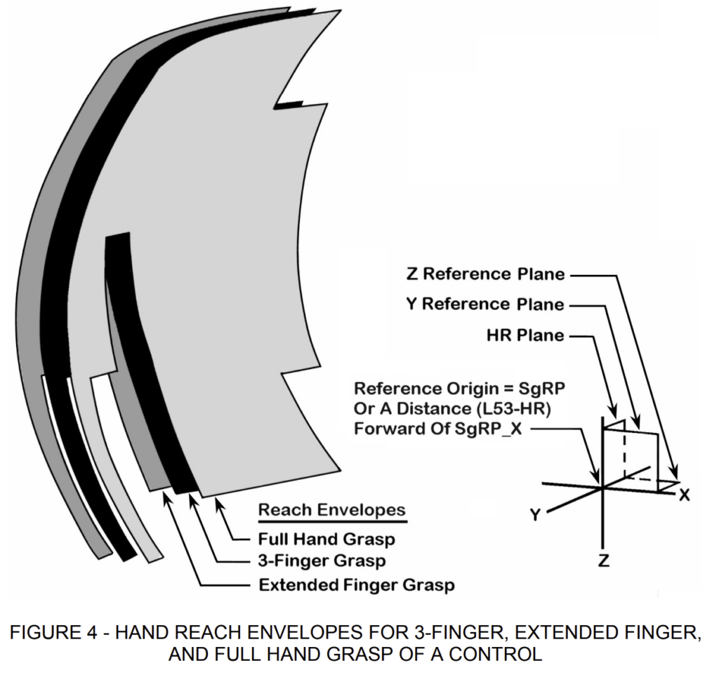
3.5 Hand Reach Reference Plane (HR Plane)
Vertical reference plane extending laterally across the vehicle (an X-plane) used to properly position the hand reach envelopes with respect to the geometry of the vehicle seating configuration. The horizontal location of the HR plane rearward of the Accelerator Heel Point depends on the value of the General Package Factor (G) as shown below:
HR = 786 – (99) G, mm (Eq. 1)
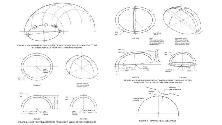
3.6 General Package Factor (G) Single index value that characterizes the geometry of the driver seating configuration for a particular vehicle. See Figures 2 and 3.
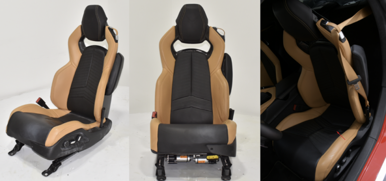
3.7 Type 1 Seat Belt Assembly
Lap belt for pelvic restraint.
3.8 Type 2 Seat Belt Assembly
Combination of pelvic (lap belt) and upper torso (shoulder belt) restraints.
3.9 Type 2a Shoulder Belt
Separate upper torso restraint (shoulder belt) intended to be used in conjunction with a lap belt to form a Type 2 seat belt assembly.
3.10 Unrestrained Reach
Hand reach with no upper torso restraint, as provided by Type 1 seat belt assembly.
3.11 Restrained Reach
Hand reach with upper torso restraint provided by a Type 2a shoulder belt. Restrained reach data were collected using a non-extending Type 2a shoulder belt with approximately 50 mm slack in the belt [Hammond and Roe, 1972].
FIELD OF APPLICATION
4.1 This practice is primarily directed towards the initial design stages of a new vehicle program, once the Seating Reference Point (SgRP) is determined. Its application for checking purposes in actual vehicles and prototype seat models will take into account an allowable tolerance for actual H-point [SAE J826].
4.2 The hand reach envelopes are directly applicable to left hand drive vehicles designed for seated operators in full width or single width seats having fore and aft seat adjustment approximately horizontal. Application to right hand drive vehicles is assumed to be symmetrically opposite.
4.3 The hand reach envelopes are directly applicable for a three-finger grasping reach to a forward mounted control knob of 25 mm diameter. The hand reach envelopes are also applicable to other types of reach to forward controls by using an appropriate adjustment factor that will account for the mode of operation at the control (see 4.3.1, 4.3.2, and [Roe, 1972]).
4.3.1 Controls Operated by Extended Finger
An adjustment factor of 50 mm is added to the tabled values of the reach envelope in order to describe the center of the finger pad contact surface which will be within the fingertip reach of drivers. This adjustment positions the extended finger reach envelope 50 mm farther from the HR plane (see Figure 4).
4.3.2 Controls Operated by Full Hand Grasp
An adjustment factor of 50 mm is subtracted from the tabled values of the reach envelope in order to describe the center of the face of the control knob which will be within the full hand grasp reach of drivers. This adjustment positions the full hand grasp reach envelope 50 mm closer to the HR plane (see Figure 4).
REQUIRED CHARACTERISTICS
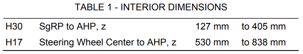
5.1 The ranges of the interior dimensions for which this recommended practice is applicable are described in Table 1.
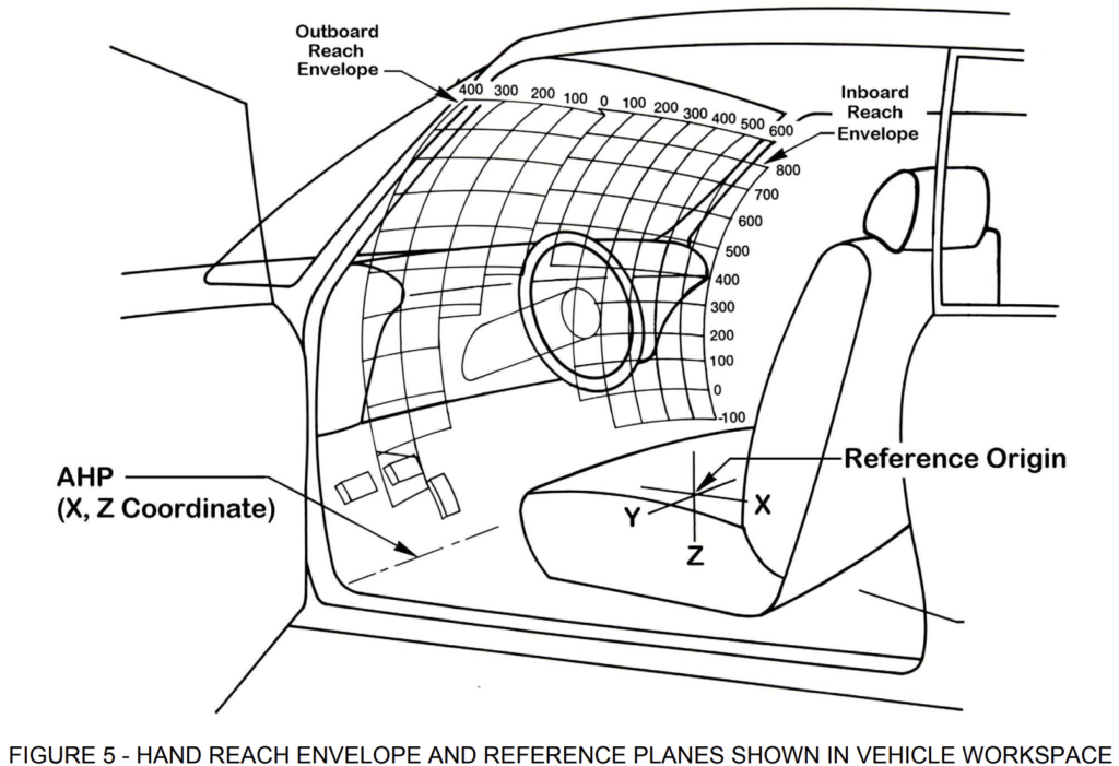
5.2 The reach envelopes describe the boundaries of control locations that can be reached by at least 95% of certain driver populations that include male-to-female driver population ratios of 50/50, 75/25, and 90/10. The envelopes for each of these categories are specified as an x-distance forward from the HR plane. The envelopes extend from 400 mm outboard to 600 mm inboard of the centerline of occupant (C/LO) and from -100 mm below SgRP to 800 mm above SgRP. See Figure 5.
5.3 Hand reach envelopes are provided in the attached tables for seven different seating configurations, three male-to-female driver population ratios, and two types of restraint systems which account for: (i) drivers wearing a lap belt only (Type 1) permitting a free upper torso motion (i.e. unrestrained torso reach); and (ii) drivers wearing both a lap and a shoulder belt (Type 2) permitting only a restrained torso reach. The selection of an envelope for a vehicle is based on the calculated value of the General Package Factor (G), identification of the male-to-female driver population ratio appropriate for the vehicle, and identification of the appropriate restraint system. The General Package Factor (G) is calculated using the dimensions describing the vehicle seating configuration shown in Figures 2 and 3.
5.4 The hand reach envelope is located in the vehicle by employing a relationship that utilizes the value of the General Package Factor (G). The horizontal component of the reach envelopes is measured as a distance forward of the HR plane. The fore and aft location of the HR plane rearward from the AHP is determined from Equation 1.
PROCEDURE FOR USING THE HAND REACH ENVELOPES
6.1 Reference Planes for Reach Envelopes: The envelopes are located in the vehicle according to a set of orthogonal reference planes: a Z-plane through SgRP, the HR plane (an X-plane), and a Y-plane through the C/LO. See Figures 4 and 5. 6.2 Establish a reference X-origin.
6.2.1 Specify the dimensions describing the geometry of the vehicle seating configuration and calculate the value of the General Package Factor (G) as described in Figure 3.
6.2.2 Calculate HR from the value of the General Package Factor (G) as shown in Equation 1.
6.2.2.1 If (HR – L53) is less than zero, then the hand reach reference plane is located longitudinally at a distance HR rearward of the AHP.
6.2.2.2 If (HR – L53) is greater than zero, the hand reach reference plane is located longitudinally at SgRP.
6.3 Identify the appropriate hand reach envelope.
6.3.1 Referring to Tables 1-42, identify the hand reach envelope appropriate for the value of the General Package Factor (G) calculated for this vehicle, the specified driver population, and the appropriate type of restraint system.
6.3.1.1 If the General Package Factor (G) value, rounded to 2 decimal places, is equal to the limit of a range, use the reach tables associated with that range.
6.3.1.2 The reach envelopes of the 50/50 male-to-female driver population ratio are recommended to establish the maximum reach for all Class A vehicles.
6.3.1.3 For vehicles with Type 2 seat belt assemblies that allow upper torso movement, use the
restrained reach envelopes (Tables 1-21) to establish the maximum reach to controls used by a driver when the vehicle is moving. For controls that are not used while driving, a considerable amount of upper torso lean may be acceptable. The unrestrained hand reach tables may be used to establish maximum reach to these controls.
6.4 Determine if the control is within reach.1
6.4.1 Determine the lateral and vertical locations of the controls of interest. Lateral locations are described as lateral distances from the C/LO. Vertical locations are the heights of the control above the SgRP.
6.4.2 The limiting value of hand reach should be read from the appropriate table at the designated elevation and horizontal station.
6.4.2.1 Interpolation may be required if the necessary control locations are not included in the table. The preferred method is to interpolate laterally then vertically. Curvilinear interpolations, using two locations on either side of the desired control, may also be considered, but minor variations in the resulting reach envelope should be expected.
6.4.3 A surface fitted through all the points in each table may also be used to determine if the control is within reach. The fitted surface should not deviate from the table values by more than 1 mm.
6.4.4 A control is considered within reach of the specified proportion of the indicated driver population if the geometric center of the control face (in the nominal or resting position) closest to the driver is tangent to or rearward of the reach contour (reach coordinates, interpolated coordinates, or fitted surface).
See the PDF at the beginning of the report to view the hand reach curved. (Table 1 – Table 42)