
Vehicle Validation Plan (DVP&R): A Worked Example
What Is Validation in the Automotive Industry?
In the life cycle of a vehicle, technology and validation plans are vital to determining customer satisfaction. The goal of validation testing is to test and confirm that the vehicle meets engineering standards and specifications prior to the vehicle hitting the dealer showroom. This also helps forecast sales estimates based on several user attributes such as performance, interior and exterior technology interfaces and styling, handling, safety features, and NVH levels.
In the automotive industry, this validation work is formally documented in what’s usually called a DVP&R, short for Design Verification Plan and Report (some companies simply call it a DVP, or Design Validation Plan). A DVP&R lists every requirement a component, subsystem, or vehicle needs to meet, the specific test used to verify it, the pass/fail criteria, and the actual results once testing is complete. Suppliers and OEMs both maintain their own DVP&Rs, and a supplier’s DVP&R has to satisfy both the relevant industry standards (SAE, ISO) and the specific OEM’s own requirements on top of that. The worked example below follows that same basic structure, walking through validation at the component, subsystem, and full-vehicle level.
Theoretical Validation Plan for a New Vehicle
As a worked example, this report summarizes a technology plan and validation plan for the theoretical prototypes of a hypothetical MY2026 Toyota Sequoia EV. For the validation plan, available prototypes would be used to gather expert and potential customer evaluation data. Potential customers and industry experts would be invited to perform the evaluation to make sure the vehicle would be a success upon its official launch in August 2025. Demographic data would be collected, including age, gender, education, profession, income, and vehicle ownership details. Participants would be asked to observe and drive the prototype and answer a checklist recording their experience with the vehicle on a 10-point scale. Finally, a vehicle buy-off ride would also be strategically planned to test the vehicle in all types of road conditions, from small windy back roads to dirt roads, city driving, and interstate highways.

Major Changes in the 2026 Toyota Sequoia EV
With the onset of improvements in battery technology and stricter emission and fuel economy norms, the MY2026 Toyota Sequoia EV needs key design changes to stay one of the favored SUVs across the USA going forward. Looking at market trends, customer reviews, and competitor vehicles such as the Chevy Tahoe and Ford Expedition, the following major changes are planned for the MY2026 vehicle:
1. Full Electric EV: With a cultural shift to electrification and green energy, automotive companies are looking at how they can manufacture more environmentally conscious vehicles. As a result, instead of the conventional IC engine-powered drivetrain, the MY2026 would be equipped with a 150kW Electric Drive Module (EDM) with a BMS-governed battery pack. The electric motor adds a total of 480 lb-ft of torque to the vehicle and is powered using a 105 kWh battery pack capacity with a skateboard design, where the platform holds the high-voltage system.

2. Increased Passenger and Cargo Volume: Based on the customer surveys carried out during the preliminary design stage (see the companion vehicle benchmarking example), one of the major concerns from current owners was the lack of sufficient leg and shoulder room in the current-generation vehicle. However, customers also don’t want the vehicle to keep growing, since a larger vehicle can become a hassle to deal with. By being meticulous with vehicle integration for MY2026, the redesign maintains the exterior dimensions of the vehicle while improving interior cargo volume and passenger packaging. The MY2026 Toyota Sequoia shows a noticeable improvement in 3rd-row occupant leg and headroom without sacrificing storage or cargo volume. With the removal of the front engine and the introduction of a high-voltage battery above the floor, the design opens up extra storage space at the front of the vehicle, also known as a “frunk.”
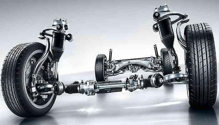
3. Active Suspension: A vehicle suspension system is a key part of determining overall vehicle comfort, by allowing each wheel to move vertically independently while constraining its movement in other directions to maintain stability and control. Vertical wheel movement from the datum position compresses the suspension system, keeping wheel movement within limits, though bump and rebound stops are encountered on the road. A suspension system is designed to keep all four wheels as nearly upright as possible at all times, not only when traveling across uneven surfaces but also when the body rolls during cornering. The suspension system must be able to interface with the body so the mass of the vehicle is properly sprung; however, the body also has to be designed to allow the integration of various vital components, which limits the available packaging space. Per feedback received during the preliminary design phase, the 2026 MY Toyota Sequoia focuses on improving suspension travel for a better ride and handling, without adversely impacting safety and durability. The customers’ voices made clear that the main requirement is a safe and durable suspension system. To meet those expectations, the MY2026 Toyota Sequoia would be equipped with adaptive front and rear suspension using magneto-rheological (MR) fluid as damper fluid. The damping characteristics of MR fluids can be varied electronically, optimizing suspension performance for any terrain at different speeds. Apart from better comfort, the adaptive suspension also reduces the possibility of rollover by adjusting suspension properties in high lateral-acceleration situations.
4. Active Safety Systems: The MY2026 vehicle would be equipped with active safety systems such as adaptive ABS, collision warning, and drowsiness alerting for improved road safety. Apart from the active safety systems, 9 airbags would be incorporated in the MY2026 Sequoia, with the extra airbags added to protect occupant knees.
5. Increased Use of Lightweight Materials in Chassis and BIW: The BIW and chassis of a vehicle are two of the main contributors to overall vehicle mass, accounting for over 60% of vehicle mass. As a result, automakers are always looking at ways to reduce the overall mass of the body structure and chassis without jeopardizing the vehicle’s structural integrity or performance.

There are a few common methods used to reduce overall vehicle mass. The first is changing the part geometry of a component, for example adding lightening holes, though this may increase manufacturing or labor cost.
Another common method is replacing a metal alloy with a higher-strength steel alloy; the increased strength lets automakers decrease the gauge of the component. Advances in technology have led to advanced high-strength steel, high-strength low-alloy steel, and ultra-high-strength steels, among others. These materials have excellent properties and considerable potential for improving a vehicle’s crash safety performance. If the main load-bearing components in the BIW are upgraded, a program can achieve its desired roof crush/side impact goals while also reducing overall vehicle mass. However, substituting these materials can cause weldability issues if the gauge difference between two mating parts is too large. Another potential weldability issue is that high-carbon steel and low-carbon steel have different melting temperatures, which can complicate the welding process. Depending on the alloy used, the material cost of the substituted metal can also significantly increase cost.
Finally, an automaker can also cut mass by choosing a lighter-weight, lower-density material — for example, switching from steel to aluminum reduces the weight of a component. However, it’s crucial to be cautious with joining techniques, since certain materials (such as steel and aluminum) cannot be welded together, and it’s of utmost importance that the structural integrity of the system isn’t diminished. Steel is a popular option in the automotive industry because of its relatively low cost, so switching materials will typically increase the cost of the component being manufactured. This is the same core tradeoff covered in more depth in our guide to lightweight materials in automotive design.
Technology Plan
Implementing technological changes in the Toyota Sequoia MY2026 is essential to positioning the vehicle as a market leader in the North American SUV segment. These technology changes are based on customer reviews of the 2019 model from current owners. Technological changes in any system come with their own set of challenges, and building a technology plan helps assimilate those challenges during design and find ways to tackle them. Major parameters affecting the technology plan, apart from customer needs, are the business needs of the company and government regulations, especially around fuel economy and emissions. The table below summarizes the major technology changes planned for the MY2026 vehicle by subsystem, along with the key implementation issue for each:
| Subsystem | Major Technology Change | Key Implementation Issue |
|---|---|---|
| Powertrain | Conversion from ICE to full battery-electric drivetrain (150kW EDM, 105 kWh pack) | Keeping powertrain and battery system cost within the program’s cost limit |
| Chassis | Skateboard battery pack integration with weight reduction via advanced high-strength steel | Sourcing reliable AHSS suppliers while meeting EPA, CAFÉ, NHTSA, and FMVSS crash, emissions, and weight standards |
| Safety | Full active safety suite, off-road ABS mode, polarized windshield | Sourcing durable polarizing film material; integrating systems without excessive cost increase |
| Lighting | Adaptive and swiveling headlights | Designing swiveling headlights that stay low-maintenance in snowy or dusty conditions |
| Packaging | New mounting positions for the electric motor and battery pack | Integrating the new component positions within the existing chassis and body design |
Conclusions and Challenges of the Technology Plan
This vehicle concept was developed considering changes in major vehicle subsystems.
1. Changes in the powertrain subsystem and conversion from conventional ICE to battery EV mainly focus on the vehicle’s fuel economy as well as its power and torque outputs, with tailpipe emission norms as the top priority. Since all these changes align with customer needs and future market trends, the major issue lies in ensuring the implemented changes don’t exceed the cost limit for the powertrain and battery system.
2. The chassis system for the Toyota Sequoia 2019 exceeded expectations in terms of safety, earning a 5-star rating, so the major focus for the chassis subsystem is accommodating the battery pack with the skateboard design and reducing weight without compromising crashworthiness and structural strength. By reducing the weight of the chassis system while maintaining performance parameters such as strength, road noise, and braking distance, the program aims to meet the crash, emission, and weight standards set by regulatory bodies like the EPA, CAFÉ, NHTSA, and FMVSS for this vehicle class. One way to meet this goal is by increasing the use of advanced high-strength steels, though that requires finding reliable suppliers for manufacturing, which becomes a major factor in determining the overall cost of the chassis system.
3. The safety system for the Toyota Sequoia MY2026 comes equipped with a full active safety suite that includes features such as collision detection and blind-spot detection. It also comes equipped with ABS with a dedicated off-road mode for greater yaw stability on uneven terrain. Along with the polarized windshield proposed, the major challenge lies in sourcing reliable polarizing film material that’s durable and will last throughout the life of the vehicle, alongside integrating these various safety systems without an unreasonable increase in cost.

4. The lighting system comes with major changes in headlight technology, such as adaptive and swiveling headlights. The major issue in implementing this is designing swiveling headlights that are easy to maintain and don’t need regular replacement, even in adverse snowy or dusty conditions.
5. The major technological issue in packaging the vehicle is incorporating design changes for mounting the motor and battery pack at new positions alongside the existing chassis and body design.
MY26 Toyota Sequoia Validation Plan
The validation plan for the MY26 Toyota Sequoia encompasses validation at the component, subsystem, and system assembly levels. Toyota has always been known for its dependability, and the MY26 Sequoia would be no exception. Validation activities would start once targets are set on August 7th, 2023. The purpose of this initial validation work is to ensure every assembly, down to the component level, performs as expected. As validation activities continue and the program moves up the systems engineering V model, confidence in the design builds toward the first prototype vehicle. That first prototype vehicle is scheduled for completion on December 2nd, 2024, giving the program its first true glimpse into overall vehicle performance. These prototype vehicles would be used at proving grounds by validation and calibration engineers to fine-tune and solve issues at the system and vehicle levels. Once deemed safe for public roads, the vehicles would be taken on small one-day trips where various experts conduct validation activities on key areas of the vehicle. Once ready, vehicles would be cleaned and perfected to show during customer clinics, to gauge whether the MY26 Sequoia meets customer expectations. The final validation milestone is a 4-day ride trip once the final prototypes are completed on June 30th, 2025.
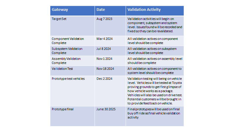

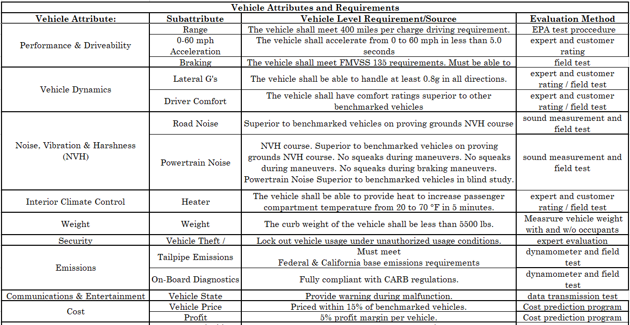
Listed in the table below is a detailed plan to validate all the key attributes of the program. With the exception of the “Customer Lifecycle,” all these validation activities would be completed before Job #1 rolls off the assembly line.


4-Day Drive Test (Final Buy-Off Ride)
As part of the final validation activity, the plan calls for a 4-day test drive with skilled engineers from different disciplines. Their role is to test every feature in the vehicle during the trip for functionality. During the trip, 8 vehicles (5 saleable builds and 3 competitive) would be used, with 4 engineers assigned per vehicle for a total of 32 engineers.
When: 1 month before Job #1 (Monday June 30th, 2025 – Thursday July 3rd, 2025)
From: Toyota North America Headquarters (Plano, TX)
To: Toyota Research Center (Ann Arbor, MI)
Engineering personnel breakdown:
- 4 from the program team (Program Engineering Manager, Assistant Program Engineering Managers)
- 1 Lead Design Engineer
- 3 Validation Engineers (1 Lead Validation Engineer, 2 Validation Engineers)
- 2 vehicle qualified managers
- 4 Infotainment software engineers
- 4 performance engineers
- 3 NVH engineers
- 2 Chassis engineers
- 4 Vehicle systems engineers
- 2 electrical engineers
- 3 manufacturing engineers (assembly plant representatives)
Engineers rotate vehicles every 2-3 hours during each stop, and also rotate between seating positions to get the most well-rounded view of each vehicle. The three passengers in each vehicle are expected to review it using the engineering validation form shown on pages 17-18. Any issue found during the buy-off ride must be recorded and presented to the executive VP of Quality for sign-off. If root cause analysis can be completed during the trip, it’s performed on the spot; otherwise, issues are sent back to the respective areas for immediate attention.
The final buy-off ride is a 4-day drive test from Toyota NA HQ in Plano, TX to the Toyota Research Center in Ann Arbor, MI. The plan calls for taking 5 saleable builds, one for each trim level offered (SR5 Base, TRD Sport, Limited, TRD Pro, and Platinum), along with 3 competitive vehicles from the competitive set for comparison to the MY26 Sequoia (Chevy Tahoe, Ford Expedition, and Nissan Armada).
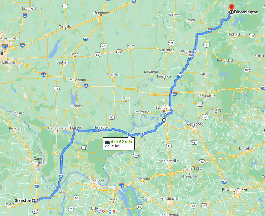
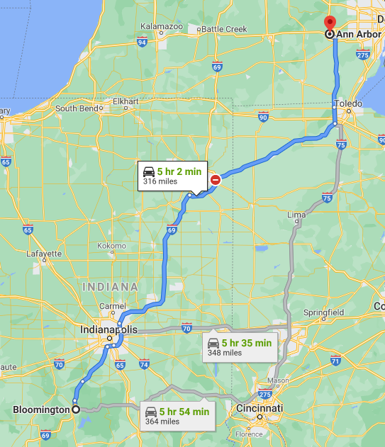
The buy-off ride is strategically planned to test the vehicle in all types of road conditions, from small windy back roads to dirt roads, city driving, and interstate highways. The route also passes through areas with very poor or no cell reception, to really test the in-car infotainment such as in-car wifi, XM Radio, and navigation. See a map of the full route below.
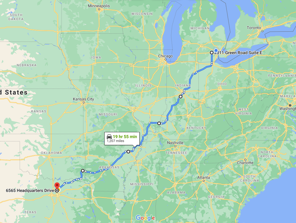
To ensure the safety of the engineers, each day involves no more than 320 miles of driving, so the vehicle can leave its starting point and reach its destination on a single charge. Each day involves roughly 5 hours of driving, with 2-3 stops for rotations to reduce fatigue. The drive is designed to test the vehicle’s performance and stress-test it under real conditions. All driving activities must be safe and must not put the driver or any passengers in harm’s way. If issues arise during the road trip, the driver is expected to pull over safely and call the Toyota hotline for towing assistance back to either Toyota HQ or the Research Center. Drivers must not take prototype vehicles to any Toyota dealership. Passengers inside the vehicle are expected to exhaust and utilize as many features of the vehicle as possible to find any potential quality or engineering-related issues. The 4-day breakdown is shown below.
Day 1: Toyota North America Headquarters (Plano, TX) to Rockwell, AR

Day 2: Rockwell, AR to Sikeston, MO

Day 3: Sikeston, MO to Bloomington, IN
Day 4: Bloomington, IN to Toyota Research Center (Ann Arbor, MI)
The validation plan could be improved by allowing additional time for all validation activities — for example, by pushing the target-set date forward, or by incorporating more virtual tools such as CAE and CFD to reduce component-assembly validation time and free up more time to validate prototype vehicles, which provide great insight into what the vehicles will actually be like. Another improvement would be fabricating more prototype vehicles, though this requires significant capital investment. As soon as a prototype vehicle is built, performance, calibration, validation, quality, and safety engineers are always competing to get their hands on it, so more prototypes would reduce wait time and increase the number of activities that could run simultaneously. More prototypes also increase build variation, which surfaces harder-to-diagnose, less common issues — issues that tend to negatively affect warranty targets. Reducing the number of these issues before mass production begins on August 4th, 2025 would significantly reduce upfront warranty cost.
Case Study: What Happens When Validation Is Skipped (GM’s Front-Wheel-Drive Transmissions)
The quality, reliability, and durability (QRD) risk of a compressed validation plan is well documented in industry history. Bob Lutz, a prominent Swiss-American automotive executive who held top leadership roles at all three U.S. “Big Three” automakers (General Motors, Ford, and Chrysler) as well as BMW, describes a striking example in his book Car Guys vs. Bean Counters. In GM’s early-1980s product program, the company converted its large cars to transverse front-wheel drive (TFWD) on an aggressive schedule, driven in part by CAFE fuel-economy requirements. Among the problems Lutz recounts was an automatic transmission, the THM440 four-speed TFWD unit, that existed on paper years earlier but had not been proven in real-world use and then failed at high rates in customer hands. He also recounts that other first-generation TFWD components, such as steering gears (the “morning sickness” cold-start lockup), air conditioning compressors, and radiators, suffered similar early failures (Lutz, 2011).
Lutz also points to a deeper cause: experienced automatic-transmission engineers, who carried the tribal knowledge of what fails and why, had been allowed to retire in the mid-1970s, so the team that designed and validated the new unit lacked that hard-won experience. The lesson for a DVP&R is straightforward. A validation plan is only as good as the test coverage, the schedule, and the people behind it. When a new architecture goes to market without enough time for component, subsystem, and full-vehicle durability testing, the validation is effectively performed by customers, and the cost shows up as warranty claims and lost brand trust. This is the same reason the MY26 plan above recommends pushing the target-set date forward or adding virtual tools to buy more prototype validation time.
Evaluation Forms and Results
An evaluation form was put together for validation engineers to evaluate the primary attributes of the vehicle. The form had each category divided into topics, subtopics, and sub-subtopics for evaluation, graded on a 1-10 scale, with 1 generally being the worst rating and 10 generally being the best, with one exception being the height of the rocker, evaluated based on how high it is, with 1 being too low, 10 being too high, and 5 being exactly the right height. Engineers are asked to evaluate the vehicle on each sub-subtopic using this scale.
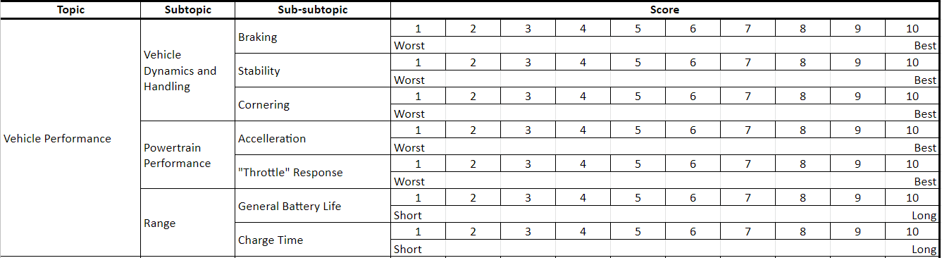

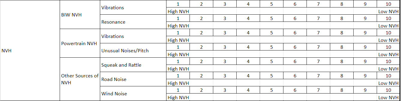

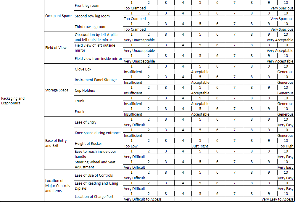
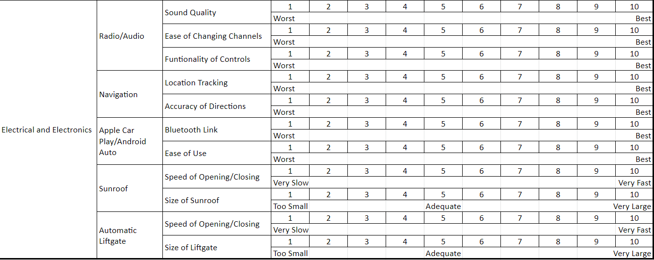
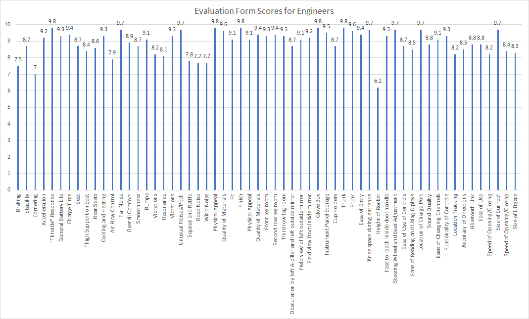
Engineers evaluate the vehicle, and their results for each sub-subtopic are collected, tallied, and averaged to determine the general consensus on the vehicle as a whole. It’s worth noting the program isn’t necessarily aiming for best-in-class in every attribute; the closer the average values are to the ideal values stated above, the better the general engineer satisfaction. These values can be visualized using a bar chart, as seen below.
Likewise, a similar evaluation form was prepared for customers. This form was simpler than the engineer version, dividing categories into just topics and subtopics, with customers asked to evaluate the vehicle on each subtopic. Again, all categories are graded on a 1-10 scale, with 1 being the worst rating and 10 being the best in all subtopics.
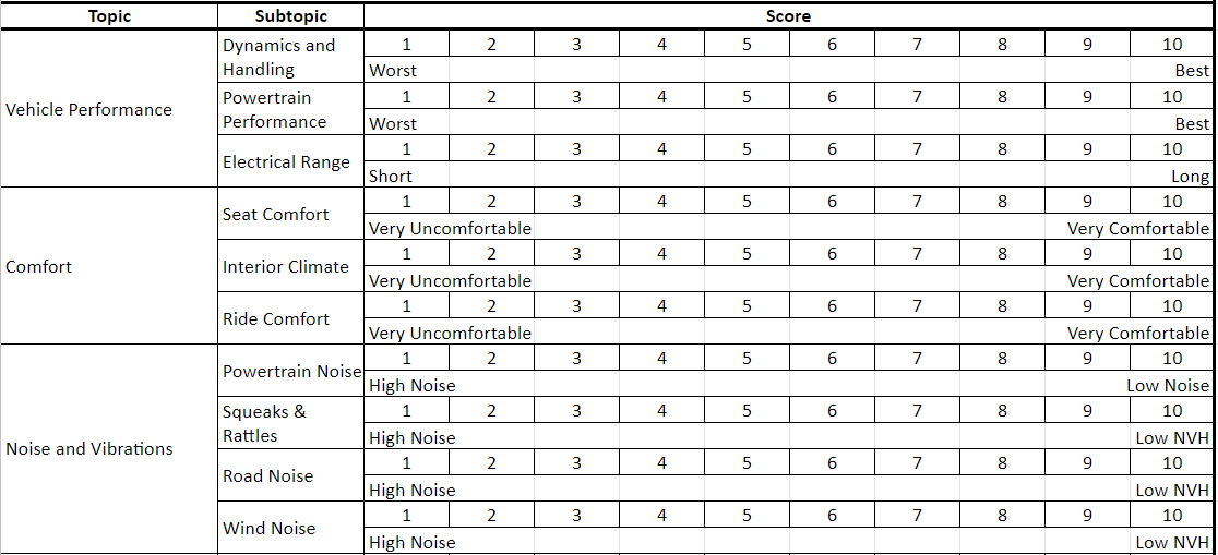
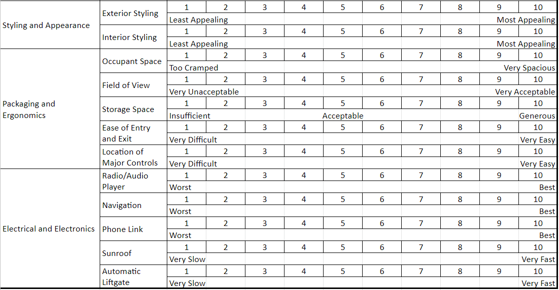
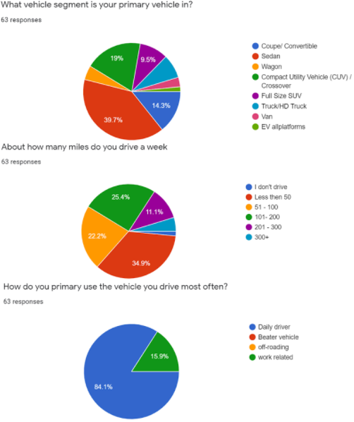
The customer results would likewise be collected and averaged, with the only real performance metric in each subtopic being how close the values are to 10. The plan aims for a broad range of demographics in the customer survey, similar to the range achieved during the preliminary design phase.


Frequently Asked Questions
What is a DVP&R?
A DVP&R, or Design Verification Plan and Report, is the industry-standard document that lists every requirement a component, subsystem, or vehicle must meet, the test used to verify each one, the pass/fail criteria, and the actual results once testing is complete. Some companies refer to it simply as a DVP, or Design Validation Plan.
What’s the difference between a validation plan and a DVP&R?
They’re generally the same thing described two different ways. “Validation plan” is the general engineering concept: a plan for confirming a design meets its requirements. DVP&R is the specific document format the automotive industry uses to capture that plan, along with the test methods, criteria, and results.
What is a vehicle buy-off ride?
A buy-off ride is one of the final validation milestones before a vehicle program reaches Job #1. Engineers from multiple disciplines drive saleable production vehicles, often alongside competitor vehicles, over a multi-day route covering varied road conditions to catch any remaining quality or engineering issues before mass production begins.
What’s the difference between component, subsystem, and system-level validation?
Component-level validation tests an individual part against its own requirements. Subsystem-level validation tests how a group of related components work together (for example, a full suspension corner). System or full-vehicle validation tests how everything performs once it’s assembled into the complete vehicle, which is where issues that only appear from component interactions tend to surface.
What is a customer clinic in vehicle validation?
A customer clinic is a validation activity where prototype or pre-production vehicles are shown to a representative sample of potential customers, who evaluate the vehicle’s attributes, usually on a rating scale, to gauge whether the design is meeting real customer expectations before launch.
References
- Automotive Product Development: A Systems Engineering Implementation, by Vivek D. Bhise. ISBN: 978-1-4987-0681-0. Publisher: CRC Press, Boca Raton, FL: CRC Press, 2017. (APD)
- Lutz, Bob. Car Guys vs. Bean Counters: The Battle for the Soul of American Business. New York: Portfolio/Penguin, 2011.
Discover more from Engineering Cheat Sheet
Subscribe to get the latest posts sent to your email.


