Sheet Metal Design Guidelines
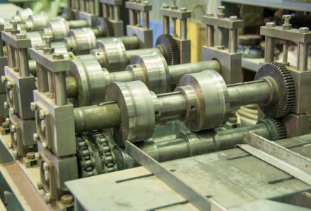
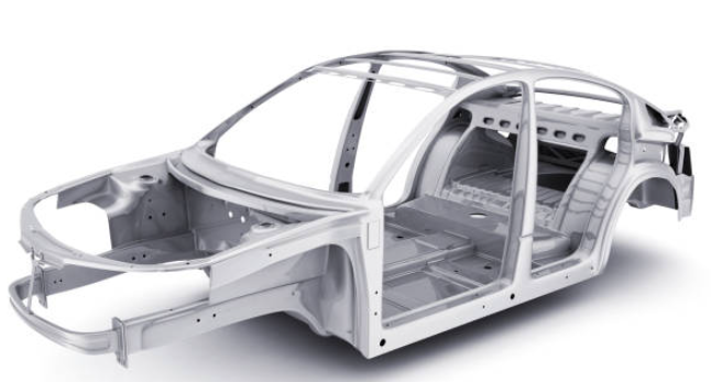
Sheet metal fabrication is a core process in modern manufacturing, widely used to produce strong, durable, and precise components for both prototyping and high-volume production. It transforms 3D CAD designs into physical parts through cutting, punching, stamping, and bending.
Adherence to well-established sheet metal design guidelines is critical to ensure manufacturability, minimize cost, maintain quality, and enhance visual appeal. The following best practices are guidelines for technical considerations to help designers produce accurate and production-ready sheet metal parts.
Manufacturing Capabilities and Resources
Several key guidelines should be followed to enhance sheet metal design, rooted in manufacturing best practices, material behavior, and industry evolution. First, understanding the material’s modulus of rupture is crucial, the maximum tensile stress in the surface of the beam when it breaks. During bending, the outer surface of the sheet experiences more strain than the inner surface, and exceeding the minimum bend radius can lead to cracking. Designers must consider this radius in relation to the sheet thickness, and in cases of larger radii, additional processing, such as polishing, may be necessary. When incorporating holes, grooves, or slots, maintaining dimensions equal to or greater than the sheet thickness ensures manufacturability and avoids tool damage. Similarly, flange width should be no less than four times the sheet thickness, and the minimum bend radius is often recommended at a 1-to-1 ratio with sheet thickness.
Additional considerations include fabrication methods such as welding, die bending, and wiping. Designers should assess whether welding is essential or if simpler alternatives, like cutting the base material or using mechanical fasteners, could achieve the same goals more efficiently. In edge-bending processes, designing with angles less than 90 degrees can reduce complexity and costs. Given the number of rules and the dynamic nature of industrial practices, utilizing Design for Manufacturability (DFM) software is highly beneficial. Such tools automate guideline checks, reduce human error, and optimize resource use, resulting in streamlined, cost-effective, and production-ready sheet metal designs.
Preferred Sheet Metal Gauge Sizes
Sheet metal is typically fabricated from materials such as mild steel, stainless steel, aluminum, and various specialty alloys, depending on the application. The selection of material plays a critical role in determining characteristics like bendability, springback, K-factor, and the wear on tooling. It is essential to choose materials that are compatible with the capabilities of the press brake and cutting equipment. The table below provides standard sheet metal gauge thicknesses for different types of steel, based on U.S. standard (English) gauge sizes, as metric sheet gauges are not widely used or readily available in the United States. Gauge sizes highlighted in the table are preferred due to their broader availability and lower cost, with recommendations guided by vendor input to help ensure faster turnaround times and more efficient sourcing.
Steel Sheet Standard Gauges
A standard steel sheet gauge chart demonstrates that thickness decreases as the gauge number increases. For instance, a 16-gauge steel sheet is thinner than a 14-gauge sheet.
This chart applies to:
Galvannealed, Cold-Rolled, and Hot-Rolled Steel
| Gauge No. | U.S. Thickness* (in) | Metric Thickness (mm) | Gauge No. | U.S. Thickness* (in) | Metric Thickness (mm) |
|---|---|---|---|---|---|
| 0 | 0.2391 | 6.073 | 17 | 0.0538 | 1.367 |
| 1 | 0.2242 | 5.695 | 18 | 0.0478 | 1.214 |
| 2 | 0.2092 | 5.314 | 19 | 0.0418 | 1.062 |
| 3 | 0.1943 | 4.935 | 20 | 0.0359 | 0.912 |
| 4 | 0.1793 | 4.554 | 21 | 0.0329 | 0.836 |
| 5 | 0.1644 | 4.176 | 22 | 0.0299 | 0.759 |
| 6 | 0.1495 | 3.797 | 23 | 0.0269 | 0.683 |
| 7 | 0.1345 | 3.416 | 24 | 0.0239 | 0.607 |
| 8 | 0.1196 | 3.038 | 25 | 0.0209 | 0.531 |
| 9 | 0.1046 | 2.657 | 26 | 0.0179 | 0.455 |
| 10 | 0.0897 | 2.278 | 27 | 0.0164 | 0.417 |
| 11 | 0.0747 | 1.897 | 28 | 0.0149 | 0.378 |
| 12 | 0.0673 | 1.709 | 29 | 0.0135 | 0.343 |
| 13 | 0.0598 | 1.519 | 30 | 0.0120 | 0.305 |
| 14 | 0.0598 | 1.519 | 31 | 0.0105 | 0.267 |
| 15 | 0.0673 | 1.709 | 32 | 0.0097 | 0.246 |
| 16 | 0.0598 | 1.519 | 33 | 0.0090 | 0.229 |
| 34 | 0.0075 | 0.191 | |||
| 35 | 0.0070 | 0.178 | |||
| 36 | 0.0065 | 0.165 | |||
| 37 | 0.0060 | 0.152 | |||
| 38 | 0.0055 | 0.140 |
Note: Preferred sizes are shaded in the source.
* U.S. Sheet thickness data sourced from J.T. Ryerson & Sons Inc. Data Book.
Stainless Steel Sheet Standard Gauges
Stainless Steel Sheet Gauges
Applies to: Cold-Rolled, Annealed & Pickled Stainless Steel
| Gauge Number | U.S. Sheets* (Decimals of an inch) | CAD Model Metric Sheet Thickness (mm) | Gauge Number | U.S. Sheets* (Decimals of an inch) | CAD Model Metric Sheet Thickness (mm) |
|---|---|---|---|---|---|
| 6 – 0’s | — | — | 17 | — | — |
| 5 – 0’s | — | — | 18 | 0.0480 | 1.219 |
| 4 – 0’s | — | — | 19 | 0.0420 | 1.067 |
| 3 – 0’s | — | — | 20 | 0.0355 | 0.902 |
| 2 – 0’s | — | — | 21 | 0.0293 | 0.744 |
| 0 | — | — | 22 | 0.0293 | 0.744 |
| 1 | — | — | 23 | 0.0250 | — |
| 2 | — | — | 24 | 0.0235 | 0.597 |
| 3 | — | — | 25 | — | — |
| 4 | — | — | 26 | 0.0178 | 0.452 |
| 5 | — | — | 27 | 0.0164 | 0.417 |
| 6 | — | — | 28 | 0.0151 | 0.384 |
| 7 | 0.1874 | 4.760 | 29 | — | — |
| 8 | 0.1650 | 4.191 | 30 | — | — |
| 9 | — | — | 31 | — | — |
| 10 | 0.1350 | 3.429 | 32 | — | — |
| 11 | 0.1200 | 3.048 | 33 | — | — |
| 12 | 0.1054 | 2.677 | 34 | — | — |
| 13 | 0.0900 | 2.286 | 35 | — | — |
| 14 | 0.0751 | 1.908 | 36 | — | — |
| 15 | — | — | 37 | — | — |
| 16 | 0.0595 | 1.511 | 38 | — | — |
NOTE: Shaded areas in the original chart represent preferred standard thickness.
*Gauge data sourced from J.T. Ryerson & Sons Inc. Data Book.
Aluminum Sheet Standard Gauges
Aluminum sheet thickness is commonly measured using a gauge system where higher gauge numbers represent thinner sheets and lower numbers indicate thicker ones. One widely used system for aluminum is the American Wire Gauge (AWG), which also incorporates the Brown and Sharpe (B&S) Gauge standard.
Aluminum Sheet Gauges
Applies to: Aluminum, Brass, and Bronze
| Gauge Number | Brown & Sharpe Aluminum* (inches) | CAD Model Metric Sheet Thickness (mm) | Gauge Number | Brown & Sharpe Aluminum* (inches) | CAD Model Metric Sheet Thickness (mm) |
|---|---|---|---|---|---|
| 6 – 0’s | — | — | 17 | 0.0453 | 1.151 |
| 5 – 0’s | — | — | 18 | 0.0403 | 1.024 |
| 4 – 0’s | — | — | 19 | 0.0359 | 0.912 |
| 3 – 0’s | — | — | 20 | 0.0320 | 0.813 |
| 2 – 0’s | — | — | 21 | 0.0285 | 0.724 |
| 0 | — | — | 22 | 0.0253 | 0.643 |
| 1 | — | — | 23 | 0.0226 | 0.574 |
| 2 | — | — | 24 | 0.0201 | 0.511 |
| 3 | 0.2294 | 5.827 | 25 | 0.0179 | 0.455 |
| 4 | — | — | 26 | 0.0159 | 0.404 |
| 5 | — | — | 27 | 0.0142 | 0.361 |
| 6 | — | — | 28 | 0.0126 | 0.320 |
| 7 | 0.1433 | 3.665 | 29 | 0.0113 | 0.287 |
| 8 | 0.1285 | 3.264 | 30 | 0.0100 | 0.254 |
| 9 | 0.1144 | 2.588 | 31 | — | — |
| 10 | 0.1019 | 2.588 | 32 | — | — |
| 11 | 0.0907 | 2.304 | 33 | — | — |
| 12 | 0.0808 | 2.052 | 34 | — | — |
| 13 | 0.0720 | 1.829 | 35 | — | — |
| 14 | 0.0641 | 1.628 | 36 | — | — |
| 15 | 0.0571 | 1.450 | 37 | — | — |
| 16 | 0.0508 | 1.290 | 38 | — | — |
NOTE: Shaded areas represent Preferred Standard Thickness
*Gauge data taken from R.J. Reynolds Aluminum Data Book
Steel Strip & Tubing Standard Gauges
A standard gauge chart for steel strip and tubing uses the Birmingham Wire Gauge (BWG) and American Standard Gauge (ASG) systems to define material thickness. In both systems, lower gauge numbers correspond to thicker materials.
| Gauge Number | Strip & Tubing Birmingham or Stubs (Decimal of an inch) | CAD Model Metric Sheet Thickness (mm) | Gauge Number | Strip & Tubing Birmingham or Stubs (Decimal of an inch) | CAD Model Metric Sheet Thickness (mm) |
|---|---|---|---|---|---|
| 6 – 0’s | — | — | 17 | 0.058 | 1.473 |
| 5 – 0’s | 0.500 | 12.700 | 18 | 0.049 | 1.245 |
| 4 – 0’s | 0.454 | 11.532 | 19 | 0.042 | 1.067 |
| 3 – 0’s | 0.425 | 10.795 | 20 | 0.035 | 0.889 |
| 2 – 0’s | 0.380 | 9.652 | 21 | 0.032 | 0.813 |
| 0 | 0.340 | 8.636 | 22 | 0.028 | 0.711 |
| 1 | 0.300 | 7.620 | 23 | 0.025 | 0.635 |
| 2 | 0.284 | 7.214 | 24 | 0.022 | 0.559 |
| 3 | 0.259 | 6.579 | 25 | 0.020 | 0.508 |
| 4 | 0.238 | 6.045 | 26 | 0.018 | 0.457 |
| 5 | 0.220 | 5.588 | 27 | 0.016 | 0.406 |
| 6 | 0.203 | 5.156 | 28 | 0.014 | 0.356 |
| 7 | 0.180 | 4.572 | 29 | 0.013 | 0.330 |
| 8 | 0.165 | 4.191 | 30 | 0.012 | 0.305 |
| 9 | 0.148 | 3.759 | 31 | 0.010 | 0.254 |
| 10 | 0.134 | 3.404 | 32 | 0.009 | 0.229 |
| 11 | 0.120 | 3.048 | 33 | 0.008 | 0.203 |
| 12 | 0.109 | 2.769 | 34 | 0.007 | 0.178 |
| 13 | 0.095 | 2.413 | 35 | 0.005 | 0.127 |
| 14 | 0.083 | 2.108 | 36 | 0.004 | 0.102 |
| 15 | 0.072 | 1.829 | 37 | — | — |
| 16 | 0.065 | 1.651 | 38 | — | — |
NOTE: Shaded Areas are the Preferred Standard Thickness
*Gauge data taken from J.T. Ryerson & Sons Inc. Data Book
Steel Wire Standard Gauges
A standard steel wire gauge chart illustrates how gauge numbers correspond to wire diameters. In this system, a lower gauge number indicates a thicker wire, while a higher gauge number represents a thinner wire.
| Gauge Number | Steel Wire Gauge (inches) | CAD Model Metric Sheet Thickness (mm) | Gauge Number | Steel Wire Gauge (inches) | CAD Model Metric Sheet Thickness (mm) |
|---|---|---|---|---|---|
| 6 – 0’s | 0.4615 | 11.722 | 17 | 0.0540 | 1.372 |
| 5 – 0’s | 0.4305 | 10.935 | 18 | 0.0475 | 1.207 |
| 4 – 0’s | 0.3938 | 10.003 | 19 | 0.0410 | 1.041 |
| 3 – 0’s | 0.3625 | 9.208 | 20 | 0.0348 | 0.884 |
| 2 – 0’s | 0.3310 | 8.407 | 21 | 0.0317 | 0.805 |
| 0 | 0.3065 | 7.785 | 22 | 0.0286 | 0.726 |
| 1 | 0.2830 | 7.188 | 23 | 0.0258 | 0.655 |
| 2 | 0.2625 | 6.668 | 24 | 0.0230 | 0.584 |
| 3 | 0.2437 | 6.190 | 25 | 0.0204 | 0.518 |
| 4 | 0.2253 | 5.723 | 26 | 0.0181 | 0.460 |
| 5 | 0.2070 | 5.258 | 27 | 0.0173 | 0.439 |
| 6 | 0.1920 | 4.877 | 28 | 0.0162 | 0.411 |
| 7 | 0.1770 | 4.496 | 29 | 0.0150 | 0.381 |
| 8 | 0.1620 | 4.115 | 30 | 0.0140 | 0.356 |
| 9 | 0.1483 | 3.767 | 31 | 0.0132 | 0.335 |
| 10 | 0.1350 | 3.429 | 32 | 0.0128 | 0.325 |
| 11 | 0.1205 | 3.061 | 33 | 0.0118 | 0.300 |
| 12 | 0.1055 | 2.680 | 34 | 0.0104 | 0.264 |
| 13 | 0.0915 | 2.324 | 35 | 0.0095 | 0.241 |
| 14 | 0.0800 | 2.032 | 36 | 0.0090 | 0.229 |
| 15 | 0.0720 | 1.829 | 37 | 0.0085 | 0.216 |
| 16 | 0.0625 | 1.588 | 38 | 0.0080 | 0.203 |
NOTE: Shaded areas represent Preferred Standard Thickness
*Gauge data sourced from J.T. Ryerson & Sons Inc. Data Book
What are the best practices for holes/cutouts in sheet metal?
When designing holes in sheet metal, they should be no smaller than the material thickness to ensure clean punching and prevent tool damage. Proper spacing from edges, bends, and other holes helps avoid deformation during manufacturing. Designers should also consider ergonomics, such as hand clearance, when holes are intended for access or manual handling.
Sheet Metal Part Design Guidelines
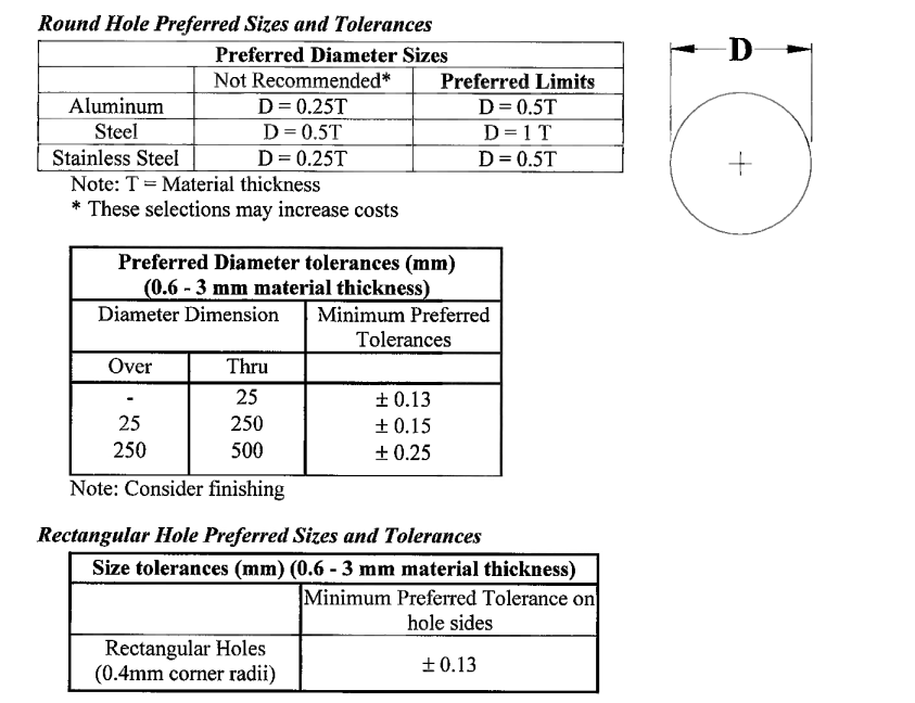
These guidelines help designers create sheet metal parts with the lowest possible built-in fabrication costs. “Preferred Limits” refer to dimensional values that minimize manufacturing expenses. While “Not Recommended” values can still be manufactured using sheet metal processes, they may lead to higher production costs.
Forming Near Holes
Holes in sheet metal can be created through punching, perforating, piercing, or laser cutting. The method used should be chosen by the approved supplier, based on which option most efficiently meets the drawing specifications and requirements defined by DX
Impact of Surface Finishes on Hole Tolerances
A. Organic Coatings: Dimensional tolerances must be applied before adding surface finishes such as paint or powder coatings.
B. Inorganic Coatings: Dimensional tolerances must be applied after applying finishes like anodizing, plating, or similar treatments.
Laser-Cut Holes
When specifying laser-cut holes, standard design principles should be followed. The shape and tolerances of laser-cut holes are generally comparable to those of punched holes.
Recommended Minimum Hole Sizes for Laser Cutting:
| Material Type | Minimum Preferred Hole Diameter |
|---|---|
| Aluminum | 0.5 × Material Thickness (T) |
| Stainless Steel | 0.5 × T |
| Carbon Steel | 1.0 × T |
Maximum Material Thickness for Laser Cutting (by Laser Power):
| Material Type | 1500 Watt Laser | 2500 Watt Laser |
|---|---|---|
| Hot/Cold Rolled Carbon Steel | 9 mm | 16 mm |
| Stainless Steel (300 Series) | 5 mm | 9 mm |
| Aluminum | 3 mm | 6 mm |
Minimum Distance Between Holes
| Material Thickness | Not Recommended* | Preferred Minimum |
|---|---|---|
| ≤ 1.5 mm | AB = 1.5T | AB = 2T |
| > 1.5 mm | — | AB = 1.5T |
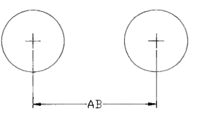
Note:
AB refers to the center-to-center distance between two adjacent holes, and T is the material thickness.
Tolerances on Dimension AB (mm)
| Over | Thru | Not Recommended* ± | Preferred ± |
|---|---|---|---|
| – | 30 | ± 0.10 | ± 0.13 |
| 30 | 100 | ± 0.10 | ± 0.13 |
| 100 | 300 | ± 0.10 | ± 0.13 |
| 300 | 600 | ± 0.15 | ± 0.25 |
| 600 | – | ± 0.25 | ± 0.40 |
* These selections may increase costs.
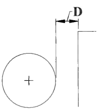
Minimum Distance from Round Hole to Blanked Edge or Rectangular Hole
(Applies only to non-captive fasteners. Use manufacturer’s guidelines for fastener holes.)
| Not Recommended* | Preferred | |
|---|---|---|
| With 1 or 2 operations | D = T | D = 3T |
| With guided punch | D = 0.5T | D = 3T |
Note: T = Material Thickness (examples: 0.3 mm, 0.7 mm, 1.0 mm)
Tolerances on Dimension D (mm)
| Over | Thru | Not Recommended* ± | Preferred ± |
|---|---|---|---|
| – | 30 | 0.09 | 0.18 |
| 30 | 100 | 0.13 | 0.25 |
| 100 | 300 | 0.18 | 0.35 |
| 300 | 1000 | 0.35 | 0.50 |
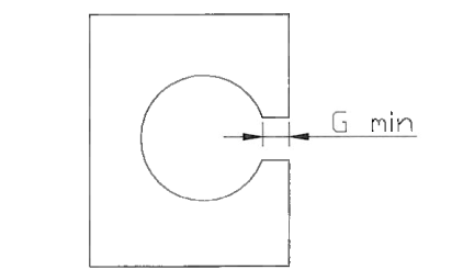
Key Hole to end of Sheet Metal
| Material Thickness | Minimum Width (Gmin) |
|---|---|
| Up to 3 mm | 2T |
| 3 mm to 10 mm | 2.5T |
Note: T = Material thickness
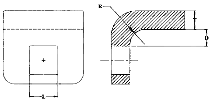
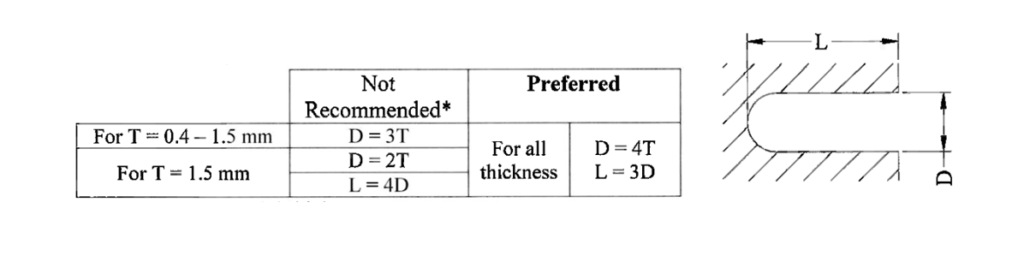
Minimum Distance from Rectangular Hole to Blanked Edge or to Another Rectangular Hole
| Condition | Not Recommended* | Preferred |
|---|---|---|
| L < 25 mm | D = T | D = 3T |
| L > 25 mm | D = 2T | D = 4T |
Note:
- T = Material Thickness
- L = Distance from hole to edge or another rectangular hole
Tolerances on Dimension D (mm)
| Over | Thru | Not Recommended* ± | Preferred ± |
|---|---|---|---|
| – | 30 | ± 0.12 | ± 0.18 |
| 30 | 100 | ± 0.12 | ± 0.25 |
| 100 | 300 | ± 0.12 | ± 0.35 |
| 300 | 600 | ± 0.25 | ± 0.50 |
| 600 | – | ± 0.40 | ± 0.50 |
How close can a hole be to a sheet metal bend?
| Condition | Not Recommended* | Preferred |
|---|---|---|
| From a round hole to an internal bend | D = 1.5T + R | D = 2T + R |
- T = Material thickness
- R = Internal bend radius
- Tolerance: ± 0.25 mm (Not Recommended), ± 0.5 mm (Preferred)
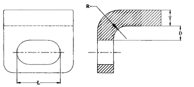
What is the minimum hole slot distance from the edge?
| Length L (mm) | Distance to Bend (D) – Not Recommended* | Distance to Bend (D) – Preferred |
|---|---|---|
| – to 25 | 2.5T + R | 4T + R |
| 25 to 50 | 3T + R | 4.5T + R |
| Over 50 | 5T + R | 7T + R |
Note: Minimum distance is from the slot to the internal bend radius
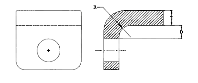
Minimum Distance from Rectangular Hole to Bend Radius
| Condition | Not Recommended* | Preferred |
|---|---|---|
| L ≤ 25 mm | D = 2T + R | D = 3T + R |
| 25 mm < L ≤ 50 mm | D = 2.5T + R | D = 3.5T + R |
| L > 50 mm | D = 3T + R | D = 4T + R |
Note: Typical tolerance on L = 0.1 mm
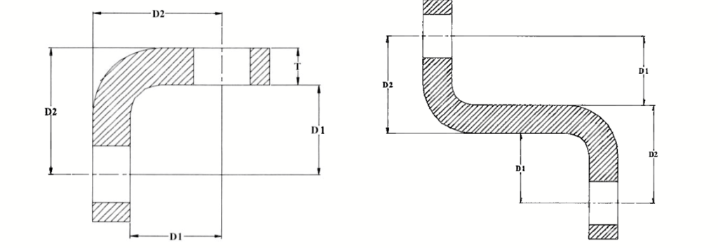
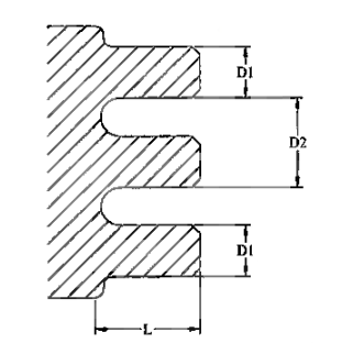
Tolerances on Hole Locations from Multiple Bends
| Dimension T (mm) | Dimension D2 Tolerance ± (mm) |
|---|---|
| 0.1 – 1.5 | ± 0.6 |
| 1.5 – 3.0 | ± 0.75 |
Note: Tolerance on D1 (inside) is ± 0.5 mm for both illustrations.
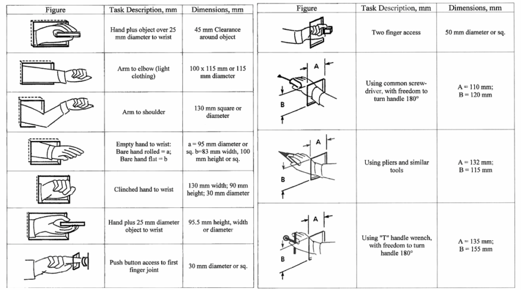
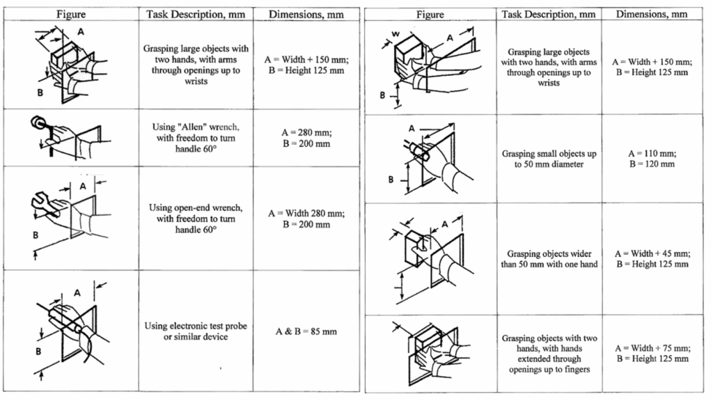
Ergonomic Operation Design Clearance
Ensuring adequate hand clearance around holes is essential for ergonomic safety and operational efficiency. It allows users to comfortably reach, grip, and manipulate objects without straining or adopting awkward postures. Effective design accounts for hole size, spacing from surrounding features, and any integrated handles to promote a secure and comfortable grip while reducing the risk of injury.
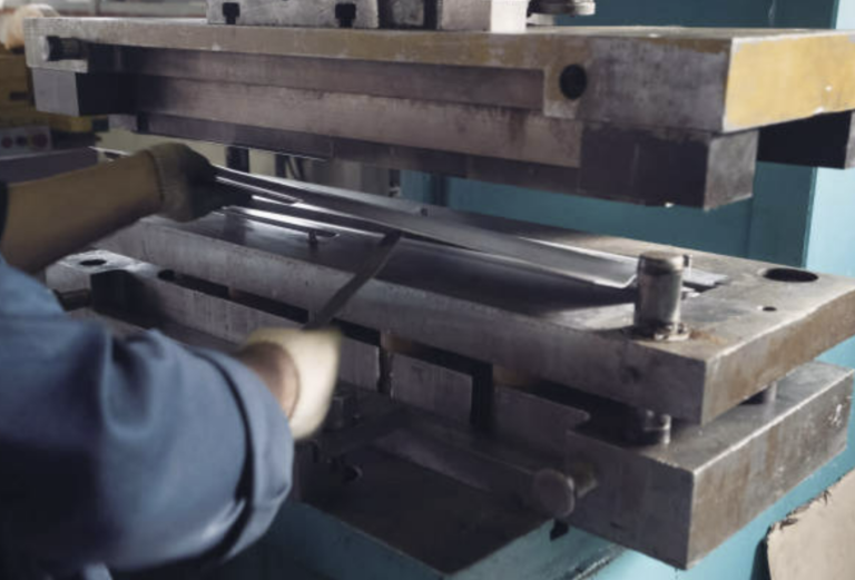
Forming, Blanking, Bending, and Burr Removal
Forming, blanking, and bending are key processes in sheet metal fabrication, whereas burr removal is typically performed as a secondary finishing step. Blanking and piercing involve the use of punches and dies to cut specific shapes from metal sheets, while bending alters the sheet’s geometry by creating curves or angles. After blanking, burr removal is often required to smooth out sharp edges, using methods such as abrasive finishing or electrochemical deburring.
Tolerances on Linear Dimensions
Typical Blank Tolerances on Linear Dimensions (mm)
| Basic Dimensions (mm) | Not Recommended* ± | Preferred ± |
|---|---|---|
| 0 – 3 | ± 0.05 | ± 0.2 |
| 3 – 6 | ± 0.05 | ± 0.2 |
| 6 – 30 | ± 0.10 | ± 0.5 |
| 30 – 120 | ± 0.15 | ± 0.8 |
| 120 – 315 | ± 0.20 | ± 1.2 |
| 315 – 1000 | ± 0.30 | ± 2.0 |
| 1000 – 2000 | ± 0.50 | ± 3.0 |
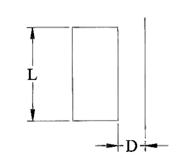
Minimum Sizes for Tabs
Minimum Sizes for Slots
Minimum Sizes for Alternating Slots and Tabs
| Dimension | Not Recommended* | Preferred |
|---|---|---|
| D1 | D1 = 4T | D1 = 5T |
| D2 | D2 = 7T | D2 = 9T |
| L | L = 2D1 | L = D1 |
Preferred Minimum Bend Radius for Carbon and Stainless Steels
| Material Type | Stock Thickness (mm) | 180° Bend Radius Minimum |
|---|---|---|
| Carbon Steel | Up to 3 | Flat on itself in either direction |
| 300 Series Stainless | Up to 2 | 1/2T |
| 400 Series Stainless | Up to 2 | 1T |
What is the minimum bend radius for aluminum?
Minimum Bend Radius for Aluminum – 90° Bends
| Stock Thickness (mm) | 90° Bend Radius (minimum) |
|---|---|
| 0 – 1 | Sharp |
| >1 – 1.5 | 0.8 |
| >1.5 – 2 | 1.6 |
| Over 2 | 2.4 |
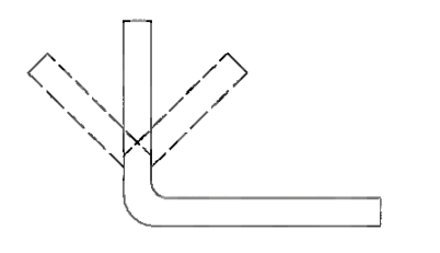
Angles and Flanges
| Not Recommended* | Preferred |
|---|---|
| Other than 90° | 90° |
Angle Tolerances
| Material Thickness | Not Recommended ±* | Preferred ± |
|---|---|---|
| 1.5 mm & below | ± 1° | ± 2° |
| All other thicknesses | ± 2° | ± 3° |
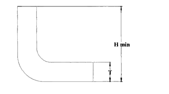
What is the minimum flange height in sheet metal?
The minimum flange height, or flange length, is defined by factors such as material thickness, the bend radius, and the specific tooling used in the forming process.
Flange Height Guidelines
| Material Thickness (mm) | Not Recommended* | Preferred |
|---|---|---|
| 0.4 – 0.8 | H = 5T | H = 6T |
| 0.8 – 3.0 | H = 4T | H = 5T |
| Over 3.0 | H = 3T | H = 4T |
Note:
- T = Material thickness
Offset Bend Tolerances
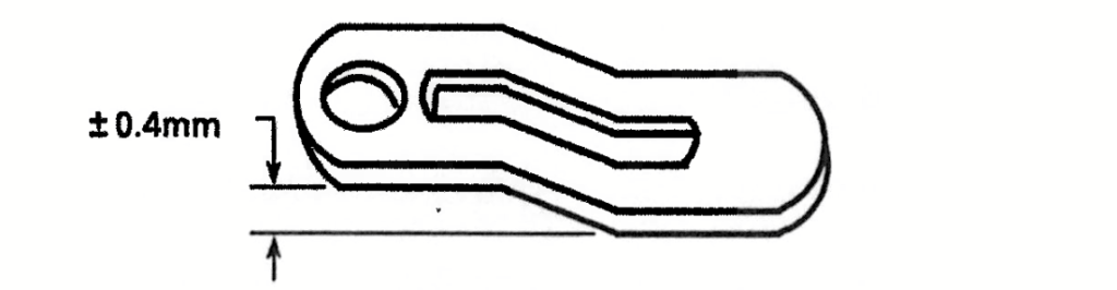
Preferred tolerance between two offset parallel flat surfaces is ± 0.4 mm
Bend Tolerances
Tolerances Between Points of Tangency
| Length L (mm) | Inside Tolerance (± mm) | Outside Tolerance (± mm) |
|---|---|---|
| 0 – 75 | 0.2 | 0.2 + (2 × mtol) |
| 75 – 600 | 0.4 | 0.4 + (2 × mtol) |
| 600 – 1200 | 0.6 | 0.6 + (2 × mtol) |
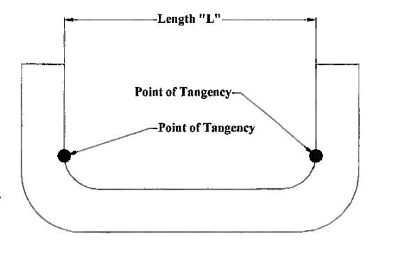
Note:
- mtol = Material thickness tolerance
- Outside tolerance = Inside tolerance + 2 × mtol
- Tolerance applies to the length between points of tangency
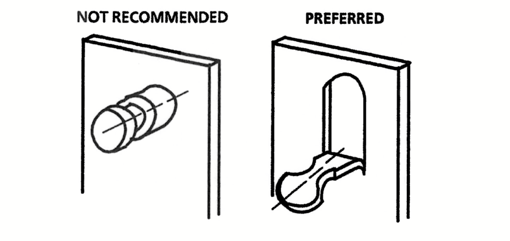
Tab Forming Guidelines
To minimize manufacturing and assembly costs, combine features into a single integrated component wherever design allows. This approach supports efficient production and aligns with Design for Assembly (DFA) principles. Avoid creating separate or unnecessary joined parts when a unified feature can achieve the same function more effectively.
Burr Removal Guidelines
- Burr removal is typically performed as a secondary process and adds extra cost to the part.
- Common burr removal methods include:
- Vibratory deburring
- Abrasive belts or wire brushes
- Barrel tumbling (note: not suitable for plated parts)
- Burrs may also be mitigated using non-removal methods, such as applying tape or installing grommets.
- Because full burr removal is expensive, designers should evaluate part application before specifying “REMOVE ALL BURRS.” Deburring should only be applied when necessary to prevent injury or meet regulatory requirements, such as UL standards for exposed edges.
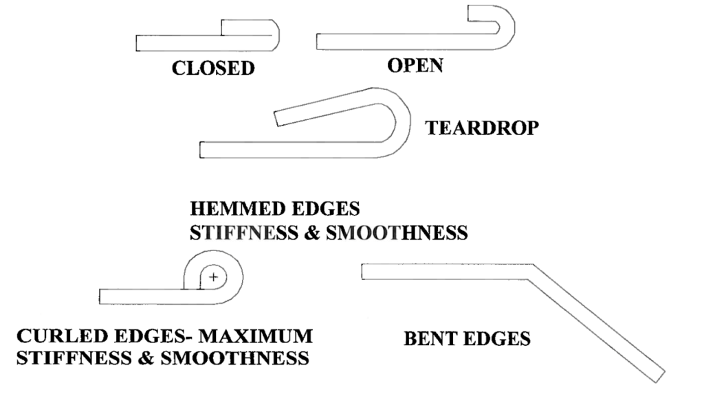
- When additional rigidity is required, hemming can be a practical alternative to deburring. Refer to “Formed Edges Stiffeners” for hemming use cases.
What are the rules for bending sheet metal?
Sheet metal bending guidelines are designed to promote uniform, cost-effective bends while preventing problems such as cracking or deformation. Essential practices include using a consistent bend radius, providing adequate bend relief, and keeping features like holes at a safe distance from bend lines.
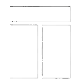
Flange Shape Examples
The range of panel bending shapes that can be achieved depends on the capabilities of the supplier’s equipment. The examples provided illustrate common panel-bending configurations and are intended to serve as initial reference points for design engineers.
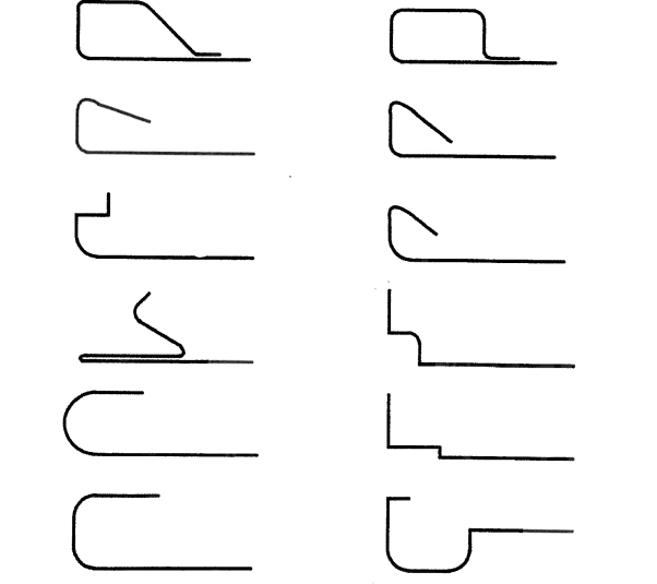
Corner and Bend Examples
The diagrams below illustrate various common corner and bend configurations used in sheet metal design. These examples serve as reference starting points for engineers during the design process.
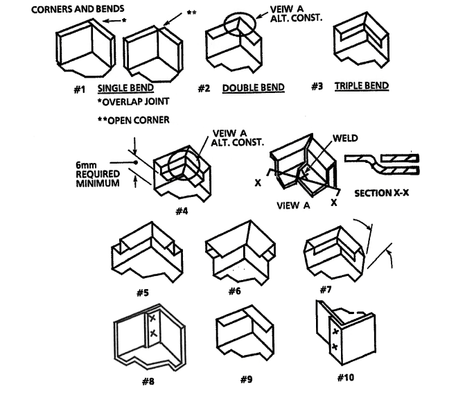
Important: Always account for and include bend relief features in your designs to ensure proper part formation and prevent deformation or tearing during fabrication.
Gaps and Joints Guidelines
- Design enclosure panel assemblies so that all gaps and joints are uniform, parallel, and maintained within ±20% of the specified nominal gap dimension.
- Ensure all gaps are backed with internal support to prevent visibility through the enclosure.
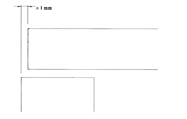
Panel Alignment Guidelines
Panels that are designed to be mounted flush should be aligned in the same plane within a tolerance of ±1 mm for every 600 mm of the panel’s maximum dimension. This ensures a consistent and professional appearance when assembled.
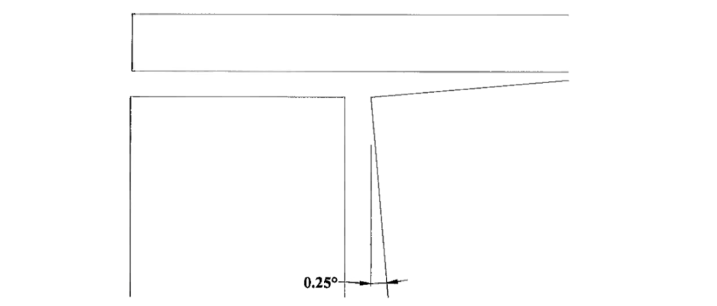
Enclosure Panel Face Angle Guidelines
Design enclosures so that, once mounted, the angles of the panel faces remain within a tolerance of ±0.25° from the specified angle.
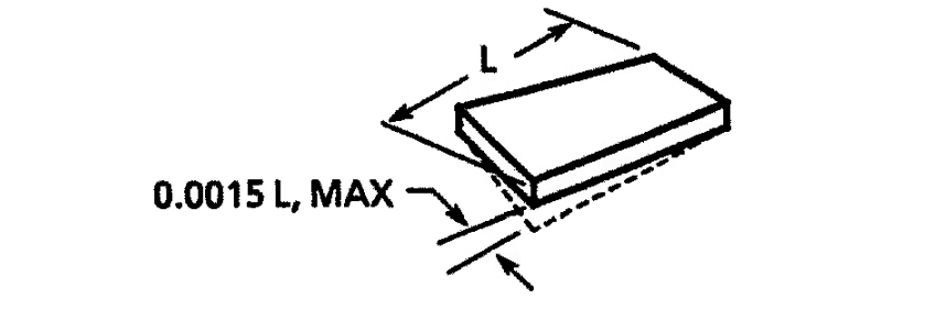
Bow and Twist Guidelines
When mounted, flat panel surfaces should maintain a combined bow and twist within a tolerance of 0.0015 times the panel’s maximum dimension to ensure proper fit and alignment.
Corner Guidelines
External corners on enclosures should have a minimum radius of 1 mm. Corners can be either welded and smoothed for a clean, finished appearance or formed without welding, based on pre-approved samples from a qualified sheet metal fabricator. While both approaches are acceptable, welding and additional finishing may increase production costs and should be evaluated before final design approval.
Approximate Cost Factor Increase
| Operation | Cost Factor |
|---|---|
| Without Welding | 1X |
| With Welding | 2X |
| With Welding & Grinding | 3X |
Stiffener Systems
Basic Stiffener Guidelines
- For parts like enclosures, covers, and aesthetic panels, minimizing finishing on the external surface helps keep costs low. Excessive welding of stiffeners, brackets, and supports can affect surface quality, especially when material thickness requirements are not followed.
- Using thinner gauge material for internal stiffeners allows for smaller welds and less finishing.
- Ideally, stiffeners should be made from material that is 60% to 80% of the main panel’s thickness.
- If multiple stiffeners are needed, use a consistent gauge across all stiffeners to streamline the weld schedule and reduce cost.
- Whenever possible, opt for formed-in stiffeners. These are more cost-effective than welded ones.
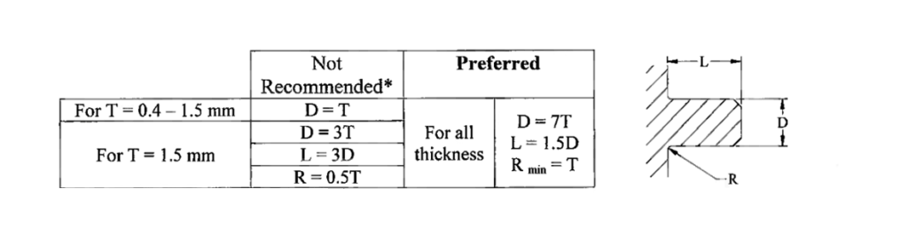
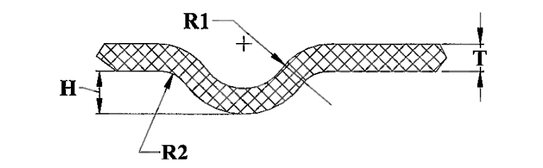
V-Bottom Rib Stiffener Dimensions
| Height (H) – dependent on material temper | Radius (R1) | Radius (R2) |
|---|---|---|
| 2T – 3T | 2T Max | 3T Max |
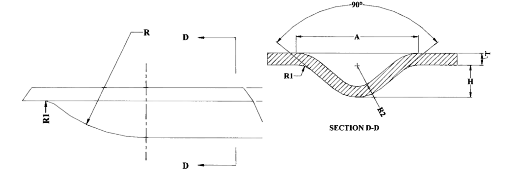
Typical Dimensions (mm)
| Material Thickness (T) | R1 | R2 | H |
|---|---|---|---|
| 0.6 mm | 2.0 | 0.4 | 2.0 |
| 0.8 mm | 2.5 | 1.2 | 2.5 |
| 1.0 mm | 2.9 | 1.4 | 2.9 |
| 1.2 mm | 3.2 | 1.6 | 3.2 |
| 1.5 mm | 3.8 | 1.9 | 3.8 |
| 2.0 mm | 4.4 | 2.3 | 4.4 |
| 2.6 mm | 4.8 | 2.5 | 4.8 |
| 3.0 mm | 4.9 | 2.8 | 4.9 |
How to stiffen a sheet metal panel?
Forming features such as flanges, hems, and beads on sheet metal greatly enhance its strength and rigidity. These methods increase the moment of inertia, improving the material’s resistance to bending. For instance, flanges create elevated edges that function like structural ribs, while hems fold the edge onto itself, providing additional reinforcement and durability.
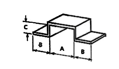
Welded Hat Section Stiffener
| Dimensions (mm) | A | B | C |
|---|---|---|---|
| 36 | 15 | 16 | |
| 48 | 15 | 10 |
Note: When spot welding stiffeners to the base material through the formed flange, ensure adequate clearance for electrode placement. A minimum preferred flange width of 15 mm (Dimension B) is recommended for proper welding access.
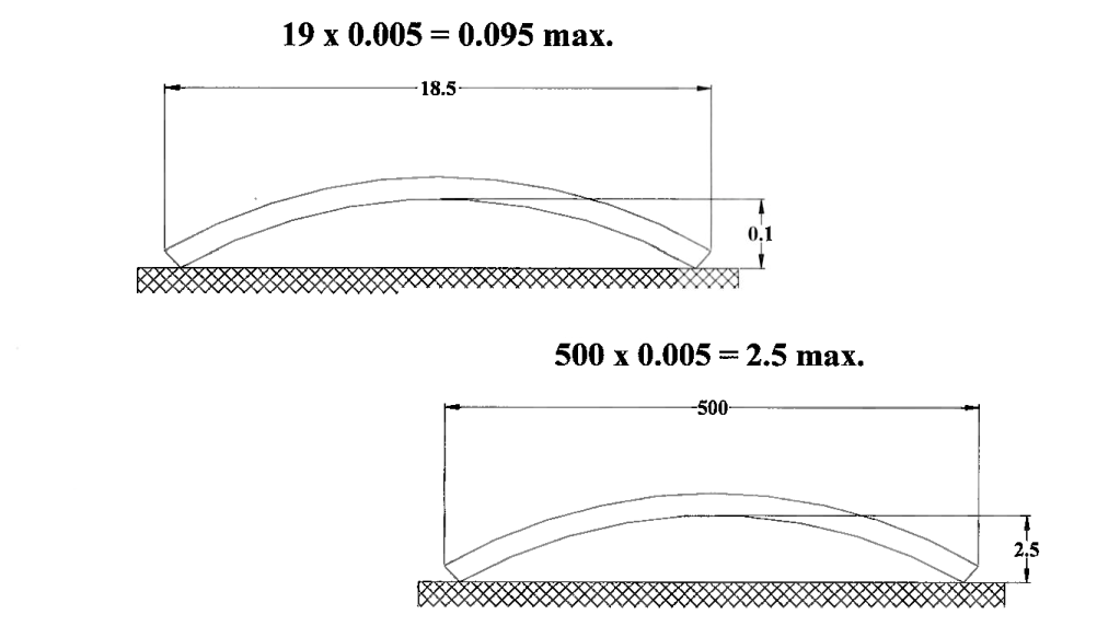
Flatness Requirements
(Refer to sheet metal drawing specifications)
Flatness deviation for a free (unclamped) surface must not exceed 0.005 times the part’s length (measured in millimeters), rounded to the nearest tenth of a millimeter. Measurements should be taken on a level, horizontal reference surface.
Example Calculation:
For a 19 mm part length:
19 × 0.005 = 0.095 mm max deviation
Threaded Fastener Systems
This guide addresses the following types of threaded fastening options:
- Plain holes
- Extruded holes with internal threads
- Clinch nuts (e.g., PEM® nuts and studs)
- For standardization, it’s recommended that each platform use either all machine screws or all thread-forming screws, wherever feasible.
- Limit the variety of hole sizes within a single design (e.g., in frame structures) to reduce tooling complexity and setup time.
Plain Hole
General Recommendations:
- Specify hole sizes to match the designated fastener, referencing standard fastener charts.
- Use the manufacturer’s punch size standards to select hole dimensions. This is particularly important when a fast turnaround is needed.
Application Benefits:
- Most commonly accepted and understood fastening approach
- Compatible with belt deburring processes
- Suitable for laser cutting production methods
Application Limitations:
- Currently, no significant limitations have been identified
Conclusion
Designing for sheet metal fabrication requires a careful balance between functionality, manufacturability, and cost-efficiency. By adhering to established sheet metal design guidelines—such as maintaining uniform material thickness, respecting minimum bend radii, and optimizing hole placement—engineers can reduce production issues, improve part quality, and shorten lead times.
While each manufacturer may have specific processes and equipment that influence their best practices, the guidelines outlined in this article serve as a strong foundation for creating effective, production-ready designs. As technology evolves and design tools advance, continuous learning and collaboration with fabrication experts will remain essential for achieving optimal results in sheet metal engineering.