SAE J1050 – Describing and Measuring the Driver’s Field of View
1. Scope
This SAE Recommended Practice establishes methods for describing and measuring the driver’s field of view. The document describes three methods for measuring the direct and indirect fields of view and the extent of obstructions within those fields. The first method uses any single pair of eye points to determine the fields or obstructions that would be seen by an individual driver. The second method uses the SAE Eyellipses defined in SAE J941 to determine the largest fields or obstructions that would be seen for a given percentage of the driving population. The third method uses specific eye points defined in SAE J941 to measure the extent of a specific field of view or obstruction for which those points were developed.
2. References
2.1 Applicable Publications—The following publications form a part of this specification to the extent specified
herein. Unless otherwise indicated, the latest issue of SAE publications shall apply.
2.1.1 SAE PU BLIC ATIO NS—Available from SAE, 400 Commonwealth Drive, Warrendale, PA 15096-0001.
SAE J264—Vision Glossary
SAE J941—Motor Vehicle Drivers’ Eye Locations
SAE J985—Vision Factors Considerations in Rear View Mirror Design
3. Definitions
3.1 Vision Origin Points
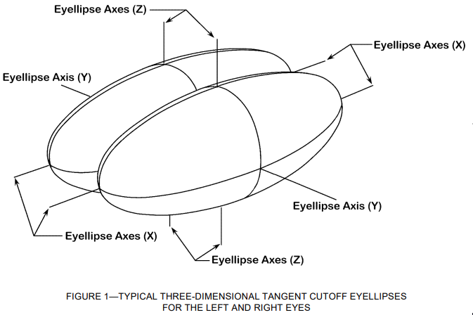
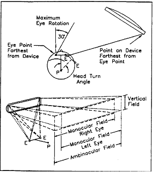
3.1.1 EYE POINT (E POINT) (FIGURE 1)—Point representing the location of the eye and from which sight lines may originate. The left and right eye points are 65.0 mm apart.
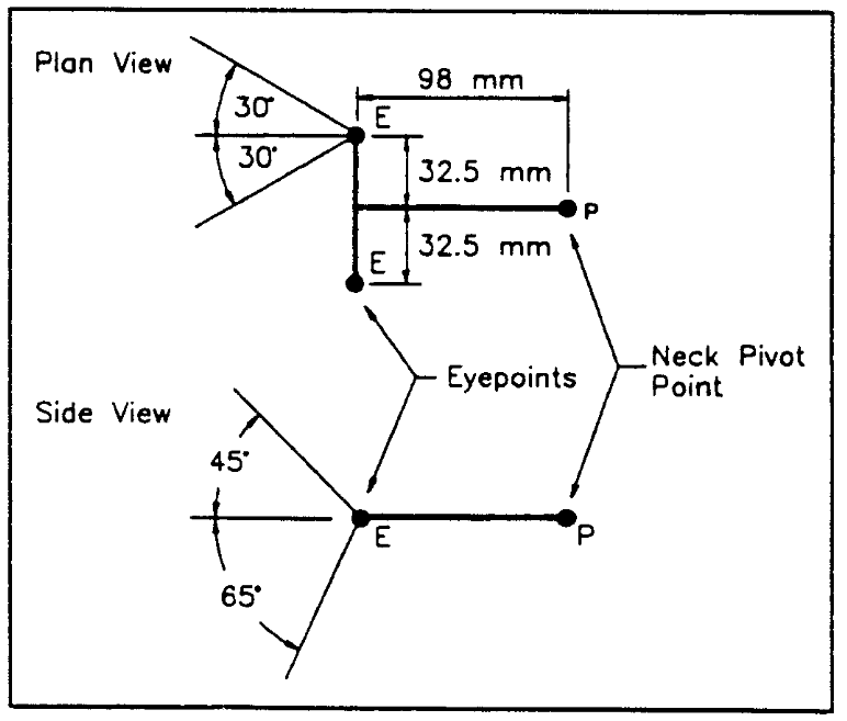
3.1.2 NECK PIVOT POINT (P POINT) (FIGURE 1)—A point about which the driver’s head turns on a horizontal plane. It is located 98 mm rearward and midway between the left and right eye points. (Appendix A)
3.1.3 VISION P POINT (V P OIN T)—A point developed and used for defining and measuring specific direct field of view requirements. (Appendix A)
3.2 Sight Line—A line representing the driver’s line of sight from an eye point or a V Point to a target point or at a given angle.
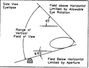
3.3 Eye Rotation
3.3.1 MAXIMUM EYE ROTATION (FIGURE 1)—The eye may rotate a maximum of 30 degrees left, 30 degrees right, 45 degrees up, and 65 degrees down from straight ahead.
3.3.2 EASY EYE ROTATION —The eye may rotate easily 15 degrees left, 15 degrees right, 15 degrees up, and 15 degrees down from straight ahead.
3.4 Head Turn
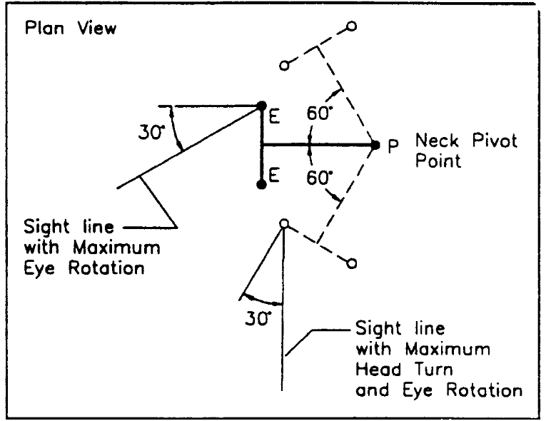
3.4.1 MAXIMUM HEAD TURN (FIGURE 2)—The driver’s head may turn about a vertical axis a maximum of 60 degrees to the left or to the right from the straight-ahead position.
3.4.2 EASY HEAD TURN—The driver’s head may quickly turn about a vertical axis 45 degrees to the left or to the right from the straight-ahead position.
3.5 Indirect Vision Device—Any device used by a driver to view a field. Examples are mirrors and video
systems.
3.6 Field of View—The solid angle is defined by sight lines originating from one or more eye points.
3.6.1 DIRECT FIELD OF VIEW —The field of view seen without the aid of any devices.
3.6.2 INDIRECT FIELD OF VIEW —The field of view seen with the use of devices.
3.6.3 MONOCULAR FIELD OF VIEW (FIGURE 3)—The field of view that can be seen by one eye.
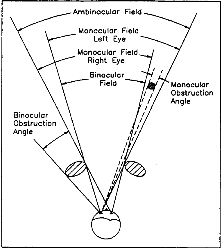
3.6.4 BINOCULAR FIELD OF VIEW (FIGURE 3)—The field of view that can be seen by both eyes simultaneously.
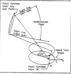
3.6.5 AMBINOCULAR FIELD OF VIEW (FIGURE 3)—The total field of view that can be seen by both eyes separately. This includes the binocular field as well as the monocular field visible to the right eye but not the left eye and vice versa.
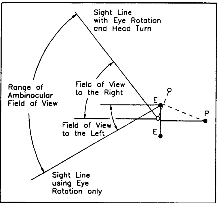
3.6.6 RANGE OF FIELD OF VIEW (FIGURE 4)—The sum of the angular fields of view to the right and left (or up and down) which can be seen by an individual driver or by the percent of drivers specified by an Eyellipse which is used. Although the same percent of drivers will see the field to the left and the field to the right (or up and down), not all the same drivers will be included in both groups.
3.6.7 PERIPHERAL FIELD OF VIEW —The field of view that extends a maximum of 90 degrees in the temporal direction.
3.7 Obstruction
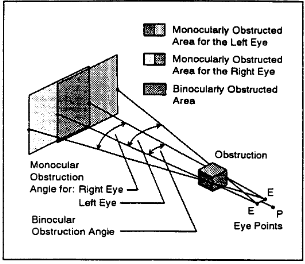
3.7.1 BINOCULAR OBSTRUCTION (FIGURE 3)—Any object within the binocular view which creates an area behind it that cannot be seen simultaneously by the left and right eyes.
3.7.2 MONOCULAR OBSTRUCTION (FIGURE 3)—Any object visible to only one eye which creates an area behind it that cannot be seen by that eye.
4. Measuring Direct Field of View
The direct field of view is measured using ambinocular vision, so any point or angle is deemed visible if at least one of the eyes can see it. Therefore, when measuring an angular field limited by an aperture (e.g., through a window), the largest angular field at any point along the aperture is that seen by the eye point farthest from the point on the aperture. The largest field to the left is found using the right eye point and the largest field to the right is found using the left eye point. When determining whether a specific point or angle can be seen within a field that is not limited by an aperture, the eye point closest to the point or angle will view the point or angle with the smallest head turn and/or eye rotation. Therefore, the right eye point should be used to view a point to the right and the left eye point used to view a point to the left.
4.1 Direct Field for an Individual Driver—If the following procedure is performed for points at the left and right limits of the field, the horizontal angle between the two sight lines is the driver’s direct ambinocular field of view. The field may be limited by an aperture or by the limits of eye rotation. Likewise, the vertical field of view may be found using the top and bottom field limits.
4.1.1 SELECT THE EYE POINT—If the field is limited by an aperture, use the eye point farther from the point on the aperture under consideration. (Figure 5) If the field is not limited by an aperture, use the eye point closer to the point or angle to be viewed. (Figure 6)
4.1.2 ROTATE THE SIGHT LINE ABOUT EYE POINT (FIGURES 5 AND 6)—Rotate the sight line about the eye point until it reaches the specified point or angle but not farther than allowed by the maximum horizontal and vertical eye rotation. If the sight line does not reach the point or angle, then it is not visible with eye rotation only.
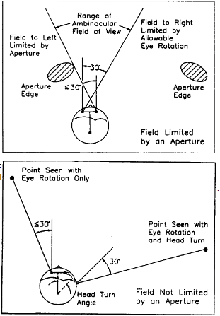
4.1.3 FIELD OF VIEW WITH EYE ROTATION ONLY—The field of view with eye rotation only is defined using the horizontal and vertical angles of the sight line from 4.1.2 or the point where the sight line intersects a target.
4.1.4 ROTATE THE SIGHT LINE ABOUT THE NECK PIVOT POINT (FIGURES 6 AND 7)—If the sight line from 4.1.2 does not pass through the specified point or does not reach the specified angle, then rotate it about the neck pivot point until it either reaches the point or angle or reaches maximum head turn. If the sight line does not reach the point or angle, then it is not visible within the limits of maximum eye rotation and head turn.
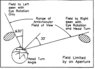
4.1.5 FIELD OF VIEW WITH EYE ROTATION AND HEAD TURN—The field of view with eye rotation and head turn is defined using the horizontal and vertical angles of the sight line from 4.1.4 or the point where the sight line intersects a target.
4.2 Direct Field for a Group of Drivers—The Eyellipses may be used to determine the largest direct field of view which will be seen by everyone within a selected group of drivers. The selected group is determined by the Eyellipse chosen. If the 95th percentile Eyellipse is used in this procedure, 95% of drivers will view at least the calculated field.
4.2.1 FIELD FOR ANY ANGLE OR POINT —Direct field of view is defined using a plane that is tangent to an Eyellipse and which either goes through the point of interest or is at the desired angle. The plane may be at any orientation relative to the coordinate system within the limits of maximum head turn and eye rotation. Because all the eye points of the selected group are on the ellipse side of that tangent plane, all drivers within the group will view at least the angle on the ellipse side of the plane. If the tangent plane contains a point on an aperture and is tangent to the side of the Eyellipse closest to the aperture point, all drivers within the group would be able to see through the aperture at the angle of the plane. The largest field through the aperture would be defined using the Eyellipse farthest from the aperture point. If the tangent plane contains a specified point in space and is tangent to the side of the Eyellipse farthest from the point, all drivers within the group would be able to see that point. The point will be seen with the least head turn and eye rotation if the Eyellipse closest to the specified point is used.
4.2.2 HORIZONTAL FIELD —The horizontal range of direct ambinocular field of view for the selected group of drivers is the horizontal angle between two vertical planes defined when the following procedure is performed for points at the left and right limits of the vision area. The limits may be those imposed by an aperture or by maximum eye rotation and head turn.
4.2.2.1 Select the Proper Eyellipse—If the field is limited by an aperture, use the Eyellipse farthest from the point on the aperture and construct the plane to the side of the Eyellipse closest to the point. (Figure 8)
If the field is not limited by an aperture, use the Eyellipse closest to the point or angle and construct the
plane to the side of the Eyellipse farthest from the point or angle. (Figure 9)
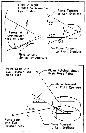
4.2.2.2 Define the Tangent Plane Within the Limits of Eye Rotation (Figures 8 and 9)—Locate a vertical plane through the point or at the specified angle and tangent to the Eyellipse. If the angle of the plane, as measured from straight ahead, exceeds that allowed by maximum eye rotation, the specified point or angle is not visible. In this case, relocate the plane tangent to the Eyellipse at the angle allowed by maximum eye rotation.
4.2.2.3 Field with Eye Rotation Only—The field of view with eye rotation only is defined by the horizontal angle of the plane.
4.2.2.4 Rotate the Plane Within the Limits of Head Turn (Figures 9 and 10)—If the vertical plane from 4.2.2.2 does not pass through the specified point or reach the specified angle, it may be further rotated about the vertical axis through the neck pivot point until it does, but not farther than allowed by maximum head turn. If the plane does not reach the point or angle, then it is not visible within the limits of maximum eye rotation and head turn.
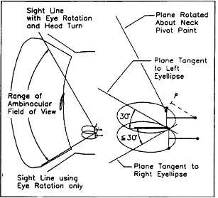
4.2.2.5 Field with Eye Rotation and Head Turn—The field of view is defined by the horizontal angle of the plane.
4.2.3 VERTICAL FIELD (FIGURE 11)—The direct vertical field of the selected group of drivers is defined using planes tangent to the Eyellipse and perpendicular to a vertical plane along the longitudinal axis of the vehicle (the Y- Z plane). The selected group will view at least the field on the ellipse side of the tangent plane. If the following procedure is performed for points at the top and bottom limits of the field, the vertical angle between the two planes defines the vertical range of the direct field of view. The limits of the field may either be those imposed by apertures or by maximum eye rotation.
4.2.3.1 Define the Tangent Plane Within the Limits of Eye Rotation—Locate a plane perpendicular to the Y-Z plane, through a specified point or at a specified angle, and tangent to the top or bottom of the Eyellipse, whichever is closest to the point. If the plane is inclined upward or downward by an angle greater than allowed by maximum eye rotation, then the point or angle is not visible within the limits of maximum eye rotation.
4.2.3.2 Field of View—The field is defined by the angle by which the plane is inclined above or below a horizontal plane.
4.3 Method for Approximating Direct Field of View Through Windows—For the purpose of comparing the direct fields of view provided by a group of vehicles or windows of different sizes, the mid-Eyellipse centroid should be used as the most acceptable single-eye point.
5. Measuring Indirect Field of View
The field of view of an indirect vision device (i.e., mirrors, cameras) is defined using ambinocular vision. The fields may be described either using horizontal and vertical angles or areas seen on a specified target.
5.1 Field of View for an Individual Driver
5.1.1 SELECT THE EYE POINT (FIGURE 12)—Use the eye point farthest from any point on the display device and the point on the display farthest from that eye point.
5.1.2 ROTATE THE SIGHT LINE WITHIN THE LIMITS OF ALLOWABLE EYE ROTATION (FIGURE 12)—Rotate a sight line about the eye point until it either passes through the point on the display or reaches the angle allowed by maximum horizontal or vertical eye rotation.
5.1.3 ROTATE THE SIGHT LINE WITHIN THE LIMITS OF ALLOWABLE HEAD TURN (FIGURE 12)—If the sight line from 5.1.2 does not pass through the display point, rotate it about the neck pivot point until it does, but not farther than allowed by maximum head turn.
5.1.4 TRACE SIGHT LINES THROUGH THE OPTICAL SYSTEM (FIGURE 12)—Trace sufficient sight lines from the left and right eye points through the optical system to define the field of view. The field may be defined using the horizontal and vertical angles of the sight lines or the points at which they intersect a target. NOTE—For systems that use electronic sensors and display, the sight lines would be traced through the optical system from the sensor.
5.2 Field of View for a Group of Drivers—The Eyellipses may be used to determine the largest indirect field of view through a device that may be seen by everyone within a selected group of drivers. The selected group is determined by the Eyellipse chosen. If the 95th percentile Eyellipse is used in this procedure, 95% of drivers will view at least the angle calculated or the area of the target defined. The horizontal indirect ambinocular field for the group of drivers is the largest horizontal angle between two sight lines defined when the following procedure is performed for points at the left and right extremes of the vision device. Likewise, the vertical field for the selected group of drivers is the largest vertical field between the two sight lines defined when the following procedure is performed for points at the top and bottom extremes of the vision device.
5.2.1 LOCATE THE EYE POINTS (FIGURE 13)—Define one eye point at the point on either Eyellipse which is farthest from any point on the indirect vision display. Locate the other eye point in the corresponding position on the opposite Eyellipse. Locate the neck pivot point for these eye points.
5.2.2 Rotate the eye points and calculate the field using the procedures outlined in 5.1.
5.3 Field of View Using Neck Pivot Points Defined in SAE J941—A method for approximating the maximum field of view for a group of drivers using neck pivot points defined in SAE J941 is given in Appendix B.
6. Obstructions
Obstructions anywhere within the direct or indirect fields of view may be described by defining the horizontal or vertical obstruction angles or by defining areas on a specified target that are obstructed.
6.1 Obstruction in Direct Field as Seen by an Individual Driver (Figure 14)
6.1.1 SELECT THE EYE POINT—Use the right eye point for obstructions to the right and the left eye point for those on the left.
6.1.2 ROTATE THE SIGHT LINE WITHIN THE LIMITS OF EYE ROTATION —Rotate a sight line from the selected eye point until it is tangent to a point on the outboard side of the obstruction, but not farther than allowed by maximum eye rotation.
6.1.3 ROTATE THE SIGHT LINE WITHIN THE LIMITS OF HEAD TURN —If the sight line of 6.1.2 did not reach the outboard side of the obstruction, the eye points, and sight line may be rotated about a vertical axis through the neck pivot point until the sight line reaches the outboard side of the obstruction but not farther than allowed by maximum head turn.
6.1.4 Define the obstructed angle or area in one of the following ways. (Figure 14)
6.1.4.1 Monocular Obstruction Angle—The monocular obstruction angle across any section through an
obstruction is the angle between the sight lines from a single eye point to the left and right sides of the
section.
6.1.4.2 Binocular Obstruction Angle—The horizontal binocular obstruction angle across any horizontal section through the obstruction is the angle between a sight line from the right eye tangent to the right side of the section and the sight line from the left eye tangent to the left side of the section. If these lines converge or are parallel, then no obstruction exists.
6.1.4.3 Obstructed Area on a Plane—The obstructed area on a plane is found for an eye point by locating points on the plane where sight lines tangent to the periphery of the obstruction intercepts the plane. The area contained within these points is the monocularly obstructed area for that eye point. The section where the obstructed area from one eye point overlaps that from the other eye point is not seen by either eye and is binocularly obstructed.
6.2 Obstructions in the Direct Field as Seen by a Group of Drivers—The Eyellipses may be used to
determine the largest obstruction angle which will be seen by anyone within a selected group of drivers. The selected group is determined by the Eyellipse chosen. If the 95th percentile Eyellipse is used in this
procedure, 95% of drivers will have their vision obstructed by not more than the maximum obstruction angle calculated.
6.2.1 MAXIMUM OBSTRUCTION ANGLE—Because of the three-dimensional nature of obstructions, the obstruction profile will differ depending on the eye points selected. The only accurate method of finding the maximum obstruction is to calculate the obstruction angle for all points on the Eyellipse which may potentially result in the maximum obstruction. Eye points are located by selecting one point on the left or right Eyellipse and locating the corresponding point on the opposite Eyellipse. The neck pivot point is located for these eye points and the obstruction is calculated using the procedure in 6.1.
6.2.2 APPROXIMATING MAXIMUM OBSTRUCTION ANGLE—To approximate the maximum obstruction angle for a group of drivers, locate the point on the Eyellipses closest to the obstruction, the corresponding eye point on the opposite Eyellipse, and the neck pivot point. Calculate the obstruction angle using the procedure in 6.1.
6.2.3 A-PILLAR OBSTRUCTION ANGLE—A method for approximating the maximum obstruction angle from the A-Pillar is given in Appendix C.
6.3 Determining the Areas on the Display and Control Surfaces Which are Not Obstructed—The Eyellipses may be used to determine the areas on a display surface which are visible to a selected group of drivers. The selected group is determined by the Eyellipse chosen. If the 95th percentile Eyellipse is used in this procedure, 95% of drivers will view at least this unobstructed area.
6.3.1 UNOBSTRUCTED AREAS—For a group of drivers, the unobstructed area is the area outside all the binocularly obstructed areas for all the eye points. To determine unobstructed areas, determine the binocularly obstructed areas on the display of interest using the procedure in 6.1 for a sufficient number of eye points on the Eyellipses to define those areas which would be obstructed for all eye points on the Eyellipse. The area outside the collection of all the binocularly obstructed areas will be visible to the selected group represented by the Eyellipse.
6.3.2 APPROXIMATING UNOBSTRUCTED AREA S—A method for approximating areas on a display surface that is not obstructed by the steering wheel, hub, and spokes is given in Appendix D.
6.4 Obstructions in the Indirect Field—The obstructed angles or obstructed areas within the indirect field are defined in the same manner as those within the direct field except that the sight lines are traced through the indirect vision device and the distance between the eye point and obstruction is measured along a sight line between them.
7. Notes
7.1 Marginal Indicia—The change bar (l) located in the left margin is for the convenience of the user in locating areas where revisions have been made to the previous issue of the report. An (R) symbol to the left of the document title indicates a complete revision of the report.