Front End Loader with Rake -Kinematic Assesment
Introduction:
The “front-end loader with rake” mechanism is an example of a heavy equipment machine used in construction and farming. Mounted on the front is a scoop or bucket connected to the end of an articulated arm. The bucket is used to scoop up material from the ground, such as snow, dirt, or feed. The rear rake is used industrially to level construction ground or for a farmer to improve the field soil. The loader assembly may have a removable or permanently mounted attachment on the back. For this mechanism, the rake was mounted permanently.
From a side view, the “front end loader with rake” mechanism consists of two motors, two drive shafts, and a drive shaft for the front-mounted bucket. A duplicate combination of shafts is located on the other side of the mechanism. The rotational motion produced by the motor is transferred to the crankshaft and driveshaft which converts the rotational motion to translational motion, and as a result, the arm connected to the bucket moves up and down. The drive shaft gives the ability to lift the bucket at a steeper angle and adds stability when weight is added. The second motor is attached to the second pair of drive shafts, which lift and lower the rake at a much lower angle. The rake only needs to be lifted a few degrees enough for it to be lifted off the ground when not in operation.
Kinematic Analysis:
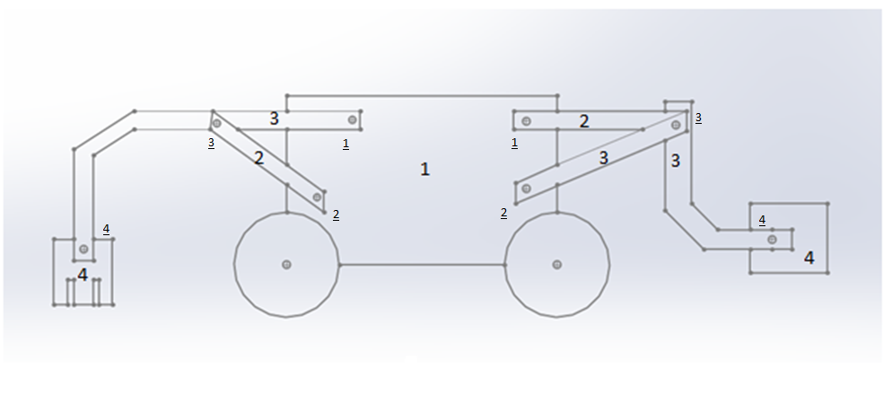
The mechanism has two degrees of freedom; one for each motor. The assembly for both the rake and the front-end loader are slider crank mechanisms. The conversion from rotational motion to translational motion means that both slider crank mechanisms resemble inversion #1. For the front-mounted bucket, two links connect it to the ground, in this case, the motor, and one full joint in the crank and drive shaft connection. According to the degrees of freedom formula (1), the four links and total full joints equal one degree of freedom. This is validated because one motor drives the bucket mechanism. Figure 1 represents the drawing of the mechanisms and number configurations of all links and full joints used in calculating the degrees of freedom. Underlined numbers indicate the numbering of a joint.
DOF=3(L-1)-J(3-dofj)
For the designed mechanism, the a total of 4 links and 4 full joints for the front-end loader as well as the rake. These kinematic conditions lead to one degree of freedom for each mechanism.
For the actual John Deere front-end loader, the degree of freedom is also 1. This is a result of the same number of links and the same number of joints.
Comparison:
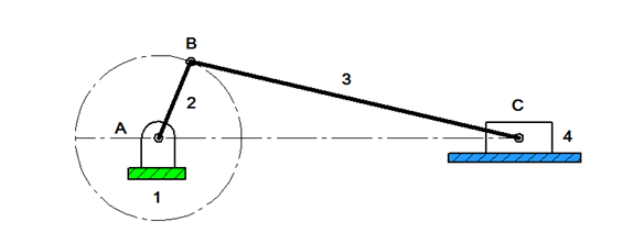
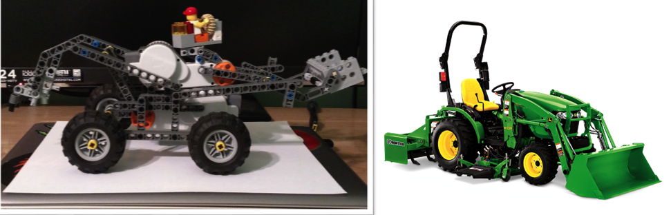
The designed mechanism and the actual have the same basic slider crank design as demonstrated in Figure 2. Each mechanism translates the motion by rotating the crank (link 2), which is connected to the coupler (link 3) and the slider (link 4). In this case, the sliding body is the front bucket, which instead of sliding motion it has vertical motion. This is caused by the bucket not being permanently fixed to the ground. Here is where the actual front-end loader differs, because the John Deere has pistons that move the bucket. The designed model did not have the bucket move, due to the limited complexity the legos had. Figure 3 is a side-by-side comparison of the model and the actual front-end loader. The motor acts as the rotational input and represents ground link 1, connection B is between the crankshaft 2 and drive shaft 3. At the end of the drive shaft is the bucket-to-ground link represented by 4.
Conclusion:
Other than the significant difference in size and material, they share many of the same internal mechanical similarities. The front bucket represents a slider-crank mechanism used to transform rotational motion into translational motion. While designing the project out of the Legos, minor modifications were made along the way but the one big modification was to the rake. Initially, the crank link connected directly to the rake. This would have meant the rake linkage would have only had three links. So to fix this the coupler was added and is connected to the crank at one end and the rake at the other end. This added the needed fourth link and completed the slider-crank mechanism used for the rake mechanism.


You’ve inspired greatness! For creators, Sprunki Game inspires greatness.
This post is pure genius! Speaking of genius, Sprunki Game is genius at play.