
Heat Sink Design: How to Size and Select a Heat Sink (Worked Example)
A heat sink, also spelled heatsink, is a passive heat exchanger that moves heat generated by an electronic or mechanical device to a fluid medium, typically air or a liquid coolant. This process helps dissipate heat away from the device, allowing for temperature regulation. The purpose of a heat sink is to keep a component’s temperature within its safe operating range by giving it a low-resistance path to the surrounding air. Heat sinks are commonly used in computers to cool CPUs, GPUs, chipsets, and RAM modules. They are also utilized with high-power semiconductor devices like power transistors, as well as optoelectronics such as lasers and LEDs, whenever the component’s own heat dissipation capacity is inadequate for temperature control.
How Do You Design a Heat Sink?
Heat sink design generally follows the same process regardless of the specific application:
- Calculate the required thermal resistance. Given the component’s power dissipation (Q) and the maximum allowable temperature rise (ΔT) above ambient, the required thermal resistance is Rth = ΔT/Q. This sets the performance target the heat sink has to hit.
- Choose a fin type. Straight (plate) fins are the simplest and cheapest to manufacture and generally dissipate the most total heat in ducted or still air. Pin fins handle omnidirectional and impinging airflow better and dissipate more heat per gram, making them a good fit for fan-cooled or cross-flow applications. Flared fins reduce flow resistance so more air actually passes through the fin channel instead of bypassing it.
- Select a material. See the material comparison below.
- Size the fin geometry (fin spacing, thickness, and height) to meet the required thermal resistance within the available footprint and airflow conditions. Fin spacing is a key trade-off: tighter spacing adds surface area but creates thinner, hotter boundary layers and more airflow resistance.
- Verify with a calculation or simulation, accounting for contact (interface) resistance between the component and the heat sink, which is often the step that’s easiest to overlook.
Heat Sink Material Selection: Aluminum vs. Copper
Aluminum and copper are the two most common heat sink materials, and the choice comes down to a cost-versus-performance trade-off:
| Material | Thermal Conductivity (W/m·K) | Relative Density | Relative Cost | Corrosion Resistance |
|---|---|---|---|---|
| Aluminum | 200 – 250 | Low (2.7 g/cm³) | Lower | Good |
| Copper | 390 – 400 | High (8.9 g/cm³) | Higher | Moderate |
Aluminum is the default choice for most heat sink designs because of its lower cost and weight. Copper’s much higher thermal conductivity makes it worth the added cost and weight when heat needs to spread quickly over a small footprint, such as directly beneath a high-power chip.
Heat Sink Design: Worked Example
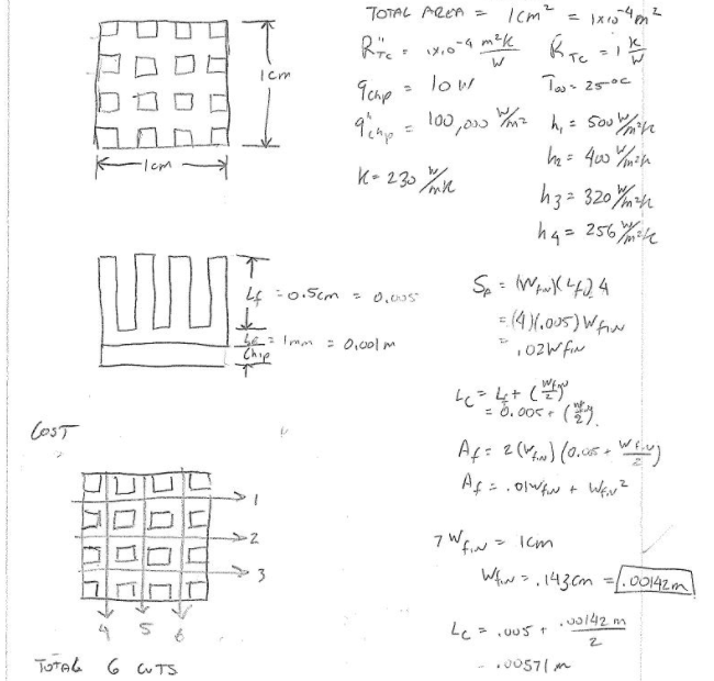
The example below applies that process to a specific case: designing a heat sink with square fins to maximize heat dissipation from a 1 cm x 1 cm computer chip. The chip receives a power input of 1 watt, and the heat sink keeps the chip cool through convection using ambient air at 25°C. There is contact resistance between the chip and the heat sink of 1 x 10⁻⁴ m²K/W.
The height of the fins is set at 0.5 cm [0.005 m]. The width of each fin must also be equal to the gaps between each of the fins. Finally, a cost was calculated based on the number of cuts needed to manufacture the heat sink, and the best design was selected. See Figure 1 (top view of a 4×4 fin array) and Figure 2 (side view of a 4×4 fin array) below.

Discussion
It was observed that as the number of columns of fins increased, the overall efficiency would increase, which allowed the chip’s steady-state temperature to be lower. To determine the temperature of the chip, equation 1 was used.
TChip = T∞ + (qchip)(Rtot) (1)
Where T∞ is equal to the temperature of the ambient air, 25[°C], qchip is equal to the electrical power being supplied to the chip, which is equal to 1[W], and Rtot is equal to the total thermal resistance of the chip [K/W]. This data was then plotted, and a correlation of exponential decay was found between the number of fins and the temperature of the chip.
The relationship that was found is that as the number of fins increased, the overall temperature of the chip decreased. With each additional layer of fins, the improvement decreased, and by the time the number of fins was increased to over 14, the temperature bottomed out around 84°C. See Figure 3 (number of fins vs. temperature and cost) below.

Conclusion
To keep the chip temperature below 115°C, a 5×5 fin design is recommended. Five fins is the minimum configuration that meets the 115°C requirement, and as shown in the bottom graph of Figure 3, fewer fins also means lower cost. As stated above, the minimum temperature found for this heat sink design was around 84°C, achieved with more than 14 fins, though at a higher manufacturing cost.
This worked example covers natural convection cooling for a small chip. For heat sinks relying on fan-driven airflow instead of natural convection, see our guide to forced convection, which covers how the convection coefficient changes with airflow and geometry.
Hand Calculations


Frequently Asked Questions
What is the purpose of a heat sink?
A heat sink keeps an electronic or mechanical component within its safe operating temperature by giving it a low-resistance path to transfer heat into the surrounding air or coolant, rather than letting that heat build up in the component itself.
How do you design a heat sink?
Heat sink design starts with calculating the required thermal resistance from the component’s power dissipation and allowable temperature rise, then choosing a fin type (straight, pin, or flared), selecting a material (typically aluminum or copper), and sizing the fin geometry (spacing, thickness, and height) to meet that thermal resistance target.
What is heat sink thermal resistance?
Thermal resistance (Rth = ΔT/Q) describes how much a heat sink’s temperature rises above ambient per watt of heat it dissipates. A lower thermal resistance means the heat sink keeps the component cooler for the same power dissipation.
Is aluminum or copper better for a heat sink?
Aluminum is lighter and cheaper and is the default choice for most designs. Copper has roughly double the thermal conductivity, making it worth the added cost and weight when heat needs to spread quickly from a small, high-power source.
Discover more from Engineering Cheat Sheet
Subscribe to get the latest posts sent to your email.


