Understanding Optical Instruments and Interference
Optics is a fascinating field of physics that deals with the behavior of light and its interactions with different media. This article explores key concepts in optical instruments, interference, and thin-film applications.
Magnifiers and Angular Magnification
A magnifier, such as a magnifying glass, enhances magnification by increasing an object’s apparent angular size as seen by the eye. This effect, known as angular magnification, allows the observer to position the object closer than usual while maintaining clear vision. As a result, the object subtends a larger angle on the retina, creating the perception of an enlarged image.

This magnification is achieved using a converging lens, which enlarges objects by producing a virtual, erect, and magnified image when the object is placed within the lens’s focal point. Unlike lateral magnification, which relates to image height, angular magnification determines how much larger an object appears when viewed through the magnifier, making it a crucial concept in optical instruments such as microscopes and telescopes.
Example
Assume that 25 cm is the closest distance at which a typical eye can focus. To determine the angular magnification (M), first, place the real object 25 cm from the eye and measure the angle it subtends, denoted as θ. Next, position the object at the focal plane of a converging lens (s = f) and observe the new angle, θ’, through the lens.
For small angles, angular magnification is given by: M=θ′/θ=25 cm/f
Since M is a ratio of angles, it is dimensionless. Here, θ represents the angle subtended by the object at 25 cm without the magnifier, while θ’ is the angle subtended when viewed through the lens. The focal length f of the converging lens, measured in centimeters, determines the degree of magnification.
What is a microscope and telescope?
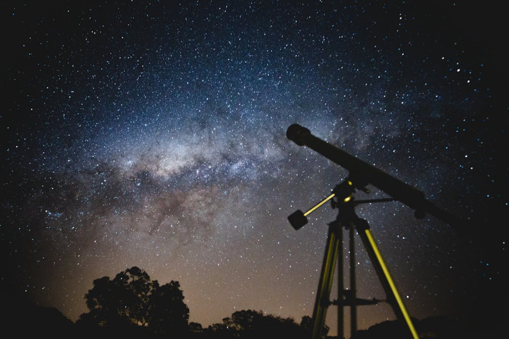
Both microscopes and telescopes enable individuals to view objects that are otherwise invisible to the naked eye. Microscopes and telescopes share a fundamental structure, as both utilize a combination of lenses or curved mirrors to focus light and magnify an image. However, telescopes are specifically designed for observing distant, faint objects. They feature larger lens diameters, longer focal lengths, and interchangeable eyepieces, allowing for enhanced magnification and clarity of celestial bodies.
What were microscopes used for?
A microscope is an optical instrument composed of multiple lenses that function according to the principles of optical imaging, allowing for the observation of objects at the microscopic level. It operates by using an objective lens to focus light on a specimen and an eyepiece to magnify and transmit the image to the human eye. By deforming light, the microscope creates the illusion of a larger appearance than the object’s actual size, making it possible to observe tiny structures such as individual cells with enhanced clarity and detail.
Microscopes utilize two lenses to achieve magnification: the objective lens forms a real image, which then serves as the object for the eyepiece, producing a magnified virtual image. The objective lens is essential for initial magnification, while the eyepiece further enlarges the image, making it visible to the observer. The overall magnification of the microscope can be adjusted by modifying the positions of these lenses, allowing for greater flexibility in observing fine details.
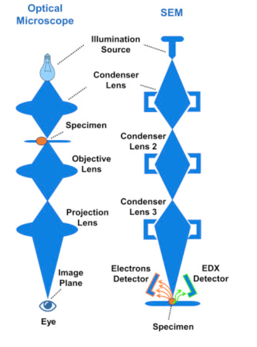
There are various types of microscopes, including light microscopes and electron microscopes, each offering different levels of magnification and resolution to suit specific observation needs. Widely used in fields such as biology, medicine, and materials science, microscopes enable the study of cells, microorganisms, nanomaterials, and other small structures, contributing significantly to scientific research and technological advancements.
What is the refracting telescope?
A refracting telescope, or refractor, is an optical telescope that uses a lens as its objective to form an image, making it a type of dioptric telescope. While similar in function to microscopes, refracting telescopes are designed for distant observations, providing high angular magnification. Originally developed for spyglasses and astronomical studies, they are also commonly used in long-focus camera lenses.
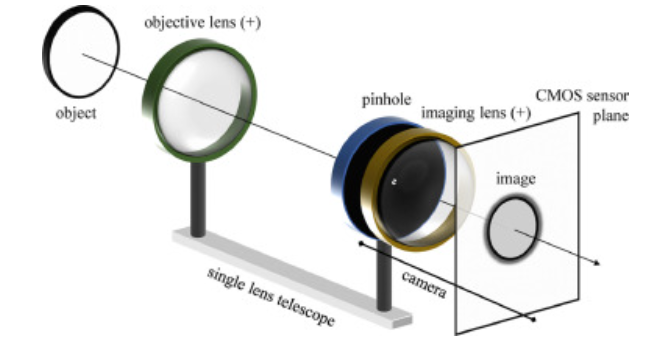
The classic planetary telescope is the long-focus refractor, known for its optical quality and effectiveness in planetary observation. One key advantage of refractors is the absence of a central obstruction (such as a secondary mirror), which allows for better contrast at a given aperture, enhancing the clarity of planetary details.
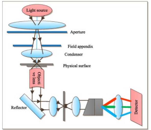
Physical Optics
Physical Optics (PO) is a method in optics and electromagnetics used to analyze the behavior of light and electromagnetic waves, particularly in high-frequency applications. Introduced by Macdonald in 1913, it involves integrating the surface electric current density induced by the magnetic field of an incident wave over the illuminated part of the scatterer.
What is a monochromatic light example?
Monochromatic light consists of a single frequency (f) and a corresponding vacuum wavelength (λ₀). A laser beam is the most recognizable example of monochromatic light. It is generated from a single atomic transition, producing light of a specific wavelength, resulting in a highly coherent and monochromatic beam.
What is meant by coherence in physics?
For interference to occur, the light sources must be coherent, meaning they maintain a constant phase relationship. Coherence refers to a stable phase relationship between waves in a beam of radiation with a single frequency. Two light beams are considered coherent when their phase difference remains constant, whereas they are incoherent if their phase relationship fluctuates randomly over time.
Constructive and Destructive Interference
- Constructive interference occurs when two waves arrive in phase, leading to a bright fringe.
- Destructive interference occurs when waves are out of phase (e.g., shifted by π radians), resulting in a dark fringe.
Mathematically, the phase difference (φ) between two waves depends on their path difference (r₂ – r₁) and is given by: ϕ=2π(r₂ – r₁)/λ
where λ is the wavelength of light.
Double-Slit Interference
In a double-slit experiment, two narrow slits act as coherent light sources, creating an interference pattern on a distant screen. The condition for bright fringes of light (constructive interference) Substituting r₂ – r₁ = d sin θ and φ = m(2π) we get the following equation dsinθ=mλ
where:
- d = distance between adjacent slits,
- θ = angle of the bright fringe from the central axis,
- m = order of the fringe (0, ±1, ±2, …). Note: The “m” in this equation is not the lateral magnification and not the mass, but is an integer.
- λ = wavelength of light.
Note: Note that m and θ must have the same sign (because d and λ are positive).
Thin-Film Interference
Thin-film interference occurs when light reflects off the two surfaces of a transparent film (e.g., soap bubbles or oil on water). The interference pattern depends on path difference and phase shifts upon reflection.
Phase Shifts in Thin Films
- A zero phase shift occurs when light reflects off a medium with a lower refractive index.
- A π rad (180°) phase shift occurs when light reflects off a higher refractive index medium.
The conditions for constructive and destructive interference are:
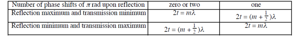
where:
- t = thickness of the film,
- m = integer (0, 1, 2, …),
- λ = wavelength in the film (λ = λ₀/n),
- n = refractive index of the film.
Michelson Interferometer
The Michelson Interferometer, invented by Michelson in the 19th century, is a key optical device used in precision measurements. It consists of a light source, beam splitter, compensation plate, two mirrors, and a detector. The device works by splitting a light beam into two paths, which are then recombined to create interference patterns.
The Michelson interferometer uses interference to measure tiny changes in optical path lengths. When the movable mirror is displaced by a distance y, the path difference changes by 2y, leading to the movement of m bright or dark fringes, given by: 2y=mλ
What are the applications of the Michelson Interferometer?
This principle is widely used in precision measurements, including wavelength determination, refractive index and sample thickness analysis, and Fourier Transform Infrared (FTIR) spectroscopy. It also plays a crucial role in atmospheric studies, measuring wind and temperature dynamics, and has been instrumental in the detection of gravitational waves, such as in LIGO experiments.
Conclusion
The study of optical instruments and interference reveals the intricate ways in which light interacts with lenses, mirrors, and various media to enhance observation and measurement. Instruments like microscopes and telescopes utilize precise optical principles to magnify objects, while technologies such as the Michelson Interferometer enable groundbreaking advancements in spectroscopy, atmospheric studies, and gravitational wave detection.
Additionally, the principles of wave interference, including constructive and destructive interference, play a crucial role in optical applications such as thin-film coatings and diffraction patterns. As optical science continues to evolve, these fundamental concepts will remain essential in driving innovation across astronomy, physics, engineering, and medical research, further expanding our ability to explore and understand the world around us.