SAE J4004 – Positioning the H-Point Design Tool
The following is a summary of SAE J4004.
Forward
This document outlines the guidelines for positioning and posturing the H-point design tool (HPD) and establishing key reference points like the seating reference point (SgRP) used in designing driver and passenger seat positions. It introduces a new method for determining driver seat track length and positioning within a vehicle, based on research from the University of Michigan Transportation Research Institute. The method accounts for variables like the presence of a clutch pedal and accommodates a range of driver statures with high statistical confidence. This practice will eventually replace an older standard (SAE J1517:1990) for Class A vehicles and applies to new vehicle designs or evaluations of existing ones.
3. Definitions
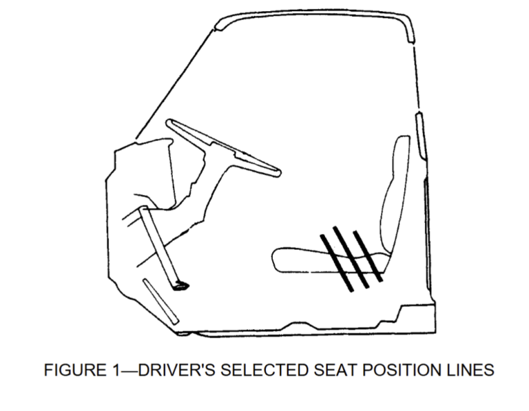
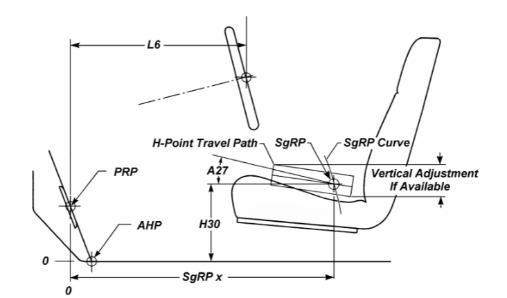
3.1 SAE J1100 Definitions (Refer to Figure 1):
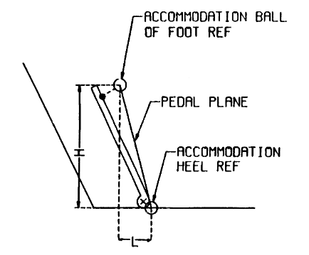
- Pedal Reference Point (PRP)
- Accelerator Heel Point (AHP)
- Floor Reference Point (FRP)
- H-point
- Seating Reference Point (SgRP)
- H-Point Travel Path
- H30 – Seat Height
- A27 – Cushion Angle
- L6 – Distance from Pedal Reference Point (PRP) to Steering Wheel Center
3.2 SAE J4004 Definitions:
3.2.2 Driver Seat Position Accommodation Point: A specific point on the design H-point travel path that ensures a certain level of driver seat position accommodation for a particular driver population and vehicle package.
3.2.1 Driver Seat Position Accommodation: The percentage of a 50/50 male/female driver population whose preferred fore/aft seat track position falls within the seat track travel path.
4. Determining the Driver Seating Reference Point and Positioning the HPD
Here’s a summary of the procedure for determining the Driver Seating Reference Point (SgRP) and positioning the H-point Design Tool (HPD):
This process involves accurately positioning the H-point Design Tool (HPD) to establish key reference points within the vehicle, including the driver’s Seating Reference Point (SgRP-Front), Pedal Reference Point (PRP), and Accelerator Heel Point (AHP). The HPD is used during vehicle design to set these points, which are crucial for configuring the vehicle’s interior. The SgRP, a critical reference for the driver’s seating position, influences various vehicle dimensions and is referenced in several standards.
The procedure includes defining initial target values for dimensions like seat height, cushion angle, and back angle. The pedal plane angle is calculated to position the shoe tool on the undepressed accelerator pedal, ensuring accurate alignment. The SgRP is positioned based on a specific curve, and the design H-point travel path is established. The process also includes adjusting the HPD’s position to ensure alignment with the vehicle’s design specifications.
5. Driver Seat Track Accommodation for a U.S. Driver Population
5.1 Determine H-Point Reference X Position
To calculate the x-distance of the H-point reference position from the Pedal Reference Point (PRP), use the following equation:
Xref=718−0.24(H30)+0.41(L6)−18.2t
- ( H30 ): Vertical distance from the Seat Reference Point (SgRP) on the H-point travel path to the Accelerator Heel Point (AHP).
- ( L6 ): Distance from PRP to the steering wheel center.
- ( t ): Transmission type (1 for vehicles with a clutch pedal, 0 for vehicles without).
5.2 Determine Seat Track Length
The seat track length determines the extent of the H-point travel path, with recommended lengths provided in Table 3 to accommodate different percentages of the driver population. For instance:
- 95% Accommodation:
- Front of H-point travel path: -116 mm
- Rear of H-point travel path: 124 mm
- Total Seat Track Length: 240 mm
A minimum seat track length of 240 mm is suggested to accommodate 95% of the driving population.
5.3 Position H-Point Travel Path in Vehicle
To position the H-point travel path in the vehicle, draw a horizontal line through the SgRP, with endpoints based on the values from Table 3. For a 240 mm seat track length, the endpoints are:
- 116 mm forward
- 124 mm rear of the H-point X-reference.
5.3.1 Add Driver Seat Position Accommodation Points (Optional)
Optional accommodation points can be added to the H-point travel path to represent various driver population levels, as detailed in Table 4.
| Percent Accommodation | Distance from Seat Track X-Reference (mm) |
|---|---|
| 1 | -135 |
| 1.25 | -131 |
| 2.5 | -116 |
| 5 | -100 |
| 10 | -79 |
| 90 | 83 |
| 95 | 106 |
| 97.5 | 124 |
| 98.75 | 140 |
| 99 | 145 |
5.3.2 Angle Seat Track in Side View
Choose a design seat track angle (A18), then rotate the H-point travel path and the accommodation points around the SgRP to match the design track angle.
5.4 Position Seat Track in Vehicle
Position the seat and seat track so that the H-point moves along the designed travel path. For seats with vertical adjustment, the travel path should align with the middle of the vertical adjustment range.
6. Design Procedures for 2nd or 3rd Row Outboard Seating Positions
This procedure outlines how to position reference points within a vehicle’s interior, such as SgRP (for second, third, or fourth-row seats), floor reference points, and floor plane angles.
To properly set the H-point design tool (HPD) for a rear seat, ensure that the seat directly in front is positioned at its SgRP. For example, to set the second-row passenger seat, the driver or front passenger seat must be at its SgRP. Similarly, the third-row passenger seat setup requires the second-row seat to be at its SgRP.
The procedure also defines the placement of the shoe and lower leg and recommends a design back (torso) angle of 25 degrees for seats with an adjustable recliner. If the seat cannot recline to this angle, use the maximum achievable angle. The SgRP for rear seats is determined by the manufacturer.
Summary of Seat Positioning Procedure
6.2 Establish Seat Positions
6.2.1 Seat Position of Seat in Front
- Position the seat directly in front of the current seat at its design location and attitude. Ensure the seat H-point aligns with the SgRP, and adjust the seat cushion and back to reflect the correct angles.
6.2.2 Current Seat Position
- For adjustable seats, position it at its design location and attitude. Set the seat back to the design angle, or use the maximum angle if it’s less than 25 degrees.
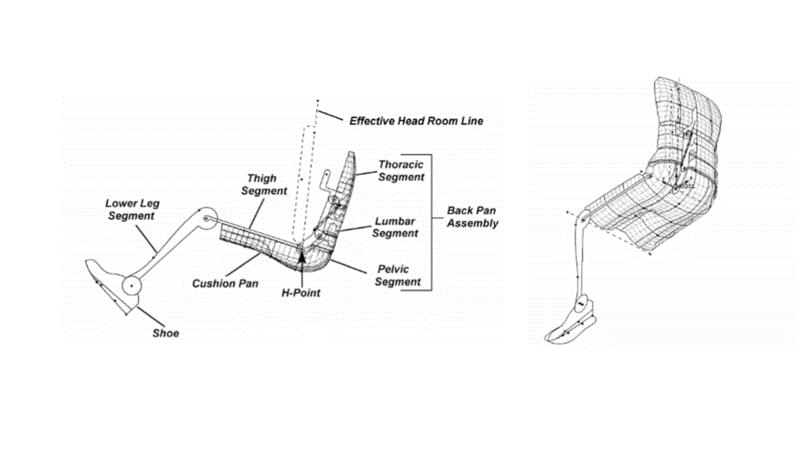
6.3 Position HPD and Determine SgRP
- Install the HPD in the seat while maintaining target values for back angle, cushion angle, and lumbar support. The H-point will define the SgRP.
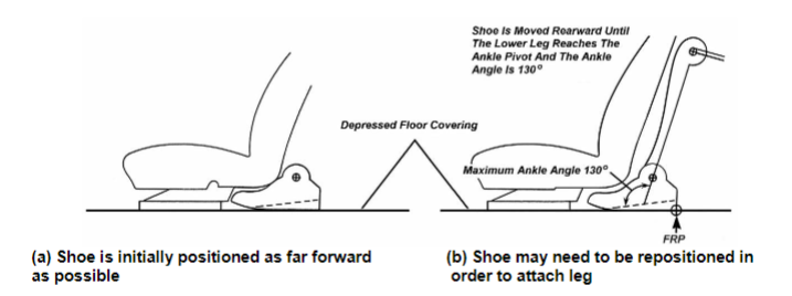
6.4 Position Shoe Tool
- Place the shoe tool on the floor with the bottom touching the depressed floor covering. Align it so the shoe centerline is within 127 mm of the occupant centerline. For long-coupled seating, move the shoe rearward to achieve a 130-degree ankle angle. This position helps establish various dimensions.
Note: In cases where the shoe does not fit between seats, position the shoe with its rear against the trim and its front intruding into the preceding seat trim.
6.5 Position Thigh and Lower Leg
- Use standard SgRP leg lengths (456 mm for thigh, 459 mm for lower leg). Position the legs while keeping the H-point on the SgRP. Ensure the y-coordinate of the leg aligns with the shoe heel and avoid lateral splay.
6.6 Short-coupled Seating
- In short-coupled seating, measure knee and leg clearance if there is interference with the preceding seat back. Use CAD data to determine these clearances and adjust measurements for any interference.
6.7 Determine Dimensions
- Measure dimensions are listed in Table 6. The FRP is the point on the floor contacted by the shoe’s heel. The shoe tool’s attitude defines the floor plane angle.
Dimensions Table 6:
- SgRP X, Y, Z Coordinates (L31, W20, H70)
- Seat Height (H30)
- Floor Reference Point Coordinates (L98, H98)
- Floor Plane Angle (A48)
- Back (torso) Angle (A40)
- Cushion Angle (A27)
- Thigh Angle (A57)
- Hip Angle (A42)
- Knee Angle (A44)
- Ankle Angle (A46)
- Effective Head Room (H61)
- Knee Clearance (L48)
- Leg Clearance (L58)
- Effective Leg Room (L51)
Adjustments may be required based on seat and seating configuration specifics.