Dynamics of Mechanical Systems
Why are the dynamics of mechanical systems important? Dynamics of mechanical systems is the science/ study of motion, aiming to describe natural and technological movements in the simplest way possible. It encompasses all aspects of motion, including displacements, deformations, and static systems where motion appears frozen. In the realm of engineering, understanding the dynamics of mechanical systems is paramount. From simple mechanisms to complex machinery, the behavior of these systems is governed by the principles of physics and mathematics.

Dynamics of mechanical systems is a science that deals with the effects of forces, whether maintaining relative rest or causing acceleration of relative motion. This division of dynamics into statics and kinetics remains a fundamental concept in both fields. As mechanical systems advance, they demand greater precision, reliability, and longevity. To meet these requirements, engineers must grasp not just the basic mechanical components, but also the principles of vibrations, stability, and balance, along with the application of Newton’s laws, Lagrange’s equations, and Kane’s methods.

This article serves as a quick crash course for understanding these concepts. Focused on theory, methods, and applications, equipping readers with a practical understanding of physical modeling, mechanical translational and rotational systems, gear trains, lossless gears, equivalent inertia, and work and power.
Physical Modeling
Physical modeling is the process of representing a physical system using mathematical equations. In the context of mechanical systems, this involves describing the motion and forces acting on the system using equations derived from Newtonian mechanics. These models are built using conservation laws (energy, mass, etc). These equations allow engineers to predict the behavior of the system under different conditions and design components to meet specific performance criteria.

What is power
In the physics and dynamics of mechanical systems, power refers to the rate of energy transfer or conversion per unit of time (Effort × flow = power). In the International System of Units (SI), power is measured in watts 𝑃 [J/s], and is a time derivative of energy 𝐸 [J]. Therefore one watt is equal to one joule per second. In older literature, power is occasionally referred to as activity. It is important to note that power is a scalar quantity, meaning it has magnitude but no specific direction.
- Energy is stored in a state of the model such as capacitors or mass.
- Energy is dissipated in ‘resistors’ such as electrical resistors or pneumatic dampers found in automotive suspension.
Mechanical Translational System
A mechanical translational system is one in which the motion of the components is linear, i.e., along a straight line. Examples of translational systems include piston-cylinder arrangements, linear actuators, and conveyor belts. The dynamics of translational systems are governed by Newton’s second law of motion. The equations of motion for any translational system are obtained by using Newton’s second law, 𝐹 = 𝑚𝑎.
- 𝐹 is the vector sum of all forces applied to each body in a system
- 𝑎 is the vector acceleration of each body w.r.t. an inertial reference frame
- 𝑚 is the mass of the body.

Translating mechanical systems are composed of three fundamental physical elements: inertia elements, springs, and friction elements. The relationships between force and position (or its derivatives) for these elements are outlined as follows:
- Inertia: 𝐹 = 𝑚a
- Spring: 𝐹 = 𝑘𝑥
- Damper/ friction element: 𝐹 = 𝑏v
Example of Mechanical Translational System
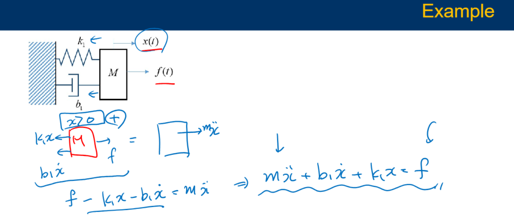
The mass-spring-damper model comprises individual mass nodes spread across an object and connected through a system of springs and dampers. It is particularly effective for simulating objects with intricate material characteristics, such as nonlinearity and viscoelasticity.
In a parallel arrangement, both the spring and dashpot (dampener) endure the same force, but their deformations combine to produce the total deformation. In a series arrangement, the spring and dashpot undergo distinct deformations, yet their forces sum up to the total applied force.
Mechanical Rotational System
A mechanical rotational system is another example of a dynamic mechanical system. In contrast to translational systems, rotational systems involve components that move in a circular or rotational motion. Examples of rotational systems include wheels, gears, and flywheels. The dynamics of rotational systems are governed by rotational analogs of Newton’s laws, which describe how torques (rotational forces) affect the angular acceleration of an object. Applying Newton’s second law, the equation of motion for a one-dimensional rotational system is obtained,𝜏 = 𝐽𝛼.
- 𝜏 is the sum of all external moments about the center of mass
- 𝛼 is the angular acceleration of each body
- 𝐽 is the mass moment of inertia of the body about the center of mass

Example of Mechanical Rotational System
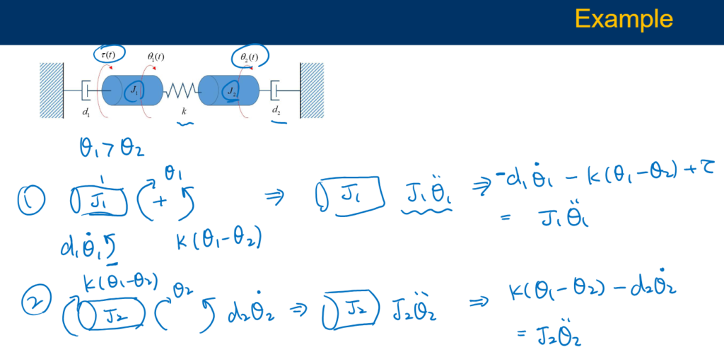
Rotational mechanical systems rotate around a fixed axis and primarily consist of three basic elements: moment of inertia (J), torsional spring (k), and dashpot (d). When a torque is applied to a rotational mechanical system, it encounters opposing torques due to the moment of inertia, elasticity, and friction of the system. The relationships between torque and angle (or its derivatives) for these elements are outlined as follows:
- Inertia: 𝜏 = 𝐽α
- Spring: 𝜏 = 𝑘𝜃
- Damper: 𝜏 = dω
In a translational mechanical system, mass serves as the means to store kinetic energy. Similarly, in a rotational mechanical system, the moment of inertia serves this purpose. When a torque is applied to a body with a moment of inertia J, it faces an opposing torque due to the moment of inertia. This opposing torque is directly proportional to the angular acceleration (α) of the body, assuming that elasticity and friction are negligible.
Dynamics of Mechanical Systems: Understanding Gear Train
A gear train is a mechanism consisting of two or more gears that mesh together to transmit motion and torque. Gear trains provide mechanical advantage to rotational systems:
- Speed reduction
- Torque amplification

As the gears turn, the distance traveled along each gear’s circumstance is the same, i.e., 𝑟1𝜃1 = 𝑟2𝜃2. Gear trains are commonly used in machinery to change the speed and direction of rotation between input and output shafts. The dynamics of gear trains are complex and involve considerations such as gear ratio, tooth profiles, and efficiency.

Lossless Gears
In idealized gear systems, all energy input is perfectly transferred to the output without any losses.
If we assume that gears are lossless (no friction loss), the gear train transmits the power/energy unchanged.

However, in real-world applications, some energy is lost due to friction, heat, and other factors. Lossless gears are a theoretical concept used in physical modeling to simplify calculations and understand the fundamental principles of gear systems.
What is a moment of Inertia?
The moment of inertia is a quantity that determines the torque needed for a desired angular acceleration about an axis of rotation. Moment of inertia is dependent on the mass distribution of the body, the larger the moment of inertia the greater the required torque to change the body’s rate of rotation.
This concept holds significance in rigid body kinetics, focusing on the forces and moments that drive both translation and rotation. The magnitude of the mass moment of inertia is crucial, as it determines a rigid body’s capacity to either maintain or resist rotational movement.
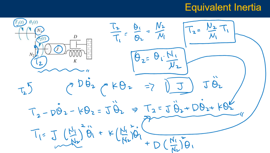
Equivalent Inertia
One of the fundamental concepts in physical modeling is the concept of inertia. Inertia is the resistance of an object to changes in its motion and is dependent on its mass. In mechanical systems, inertia plays a crucial role in determining how components move and interact with each other.
In complex mechanical systems, it is often useful to simplify the system by replacing multiple components with a single equivalent component. Equivalent inertia is a concept used to represent the combined inertia of multiple components as a single inertia value. This simplification allows engineers to analyze the system more easily and make informed design decisions.
Work vs power
In mechanical systems, work and power are fundamental concepts that describe the energy transfer and performance of the system. Work is defined as the product of the force applied to an object and the distance over which the force is applied. It is a measure of the energy transferred to or from the object and is expressed in joules (J).
Power, on the other hand, is the rate at which work is done or the rate at which energy is transferred. It is calculated as the work done divided by the time taken and is expressed in watts (W). Understanding work and power is essential for designing efficient mechanical systems, as it allows engineers to calculate the energy requirements and performance characteristics of the system.
Translational system – Force, work, and power:
𝑊 = ∫ 𝐹𝑑𝑥
𝑃 = 𝑑𝑊/𝑑𝑡 = 𝐹𝑣
Rotational system – Torque, work, and power:
𝑊 = ∫ 𝜏𝑑𝜃
𝑃 = 𝑑𝑊/𝑑𝑡 = 𝜏𝜔
Newton’s second law:
𝑚𝑑𝑉/𝑑𝑡 = 𝐹𝑑𝑟𝑖𝑣 − 𝐹𝑙𝑜𝑎𝑑
𝐽𝑑𝜔/𝑑𝑡 = 𝜏𝑑𝑟𝑖𝑣 − 𝜏𝑙𝑜𝑎𝑑
Conclusion
In conclusion, the dynamics of mechanical systems are governed by a combination of physical principles and mathematical equations. By understanding concepts such as physical modeling, translational and rotational systems, gear trains, lossless gears, and equivalent inertia, engineers can design more efficient and reliable mechanical systems.


