SAE J1052 – Motor Vehicle Driver and Passenger Head Position
The following is a summary of SAE J1052.
Forward
Foreword—Changes in This Revision—This document has been updated to align with the changes made to SAE J941 eyellipses. While the size and shape of the head position contours remain unchanged, their positioning in Class A vehicles has been adjusted upward and rearward. The procedure for locating these contours has also been revised. In the previous version, the contours were positioned relative to SgRP based on the manufacturer’s design back angle. In this revision, they are now positioned either relative to the centroid of the corresponding eyellipse or to the vehicle grid. The adjustable seat head contours are no longer based on the design back angle, and the front of the contour is now inclined downward at a steeper angle. Additionally, this version introduces head position contours for the front center seat and for front outboard seats with fixed (non-adjustable) seats. The procedure for Class B vehicles remains unchanged. Further information on the development of the head position contours can be found in Appendix A.
Scope
This SAE Recommended Practice outlines head position contours and procedures for determining their placement within a vehicle. These contours are important for establishing headspace accommodation requirements and are necessary for several measurements defined in SAE J1100. Different contours are specified based on occupant seat location and the desired level of occupant accommodation (95% and 99%).
The primary focus of this document is its application to Class A vehicles (as defined in SAE J1100), which includes most personal-use vehicles such as passenger cars, sport utility vehicles, and pickup trucks. A procedure for Class B vehicles is provided in Appendix B.
Applicable Publications
Applicable Publications—The following publications are referenced in this specification as needed. Unless stated otherwise, the most recent versions of the SAE publications will apply.
SAE Publications (available from SAE, Warrendale, PA):
- SAE J941: Motor Vehicle Drivers’ Eye Locations
- SAE J1052 (MAY87 and APR97): Motor Vehicle Driver and Passenger Head Position
- SAE J1100: Motor Vehicle Dimensions
- SAE J1516: Accommodation Tool Reference Point
- SAE J1517: Driver Selected Seat Position
- SAE Papers:
- 650464: “Automobile Driver Eye Position” (J.F. Meldrum, 1965)
- 720200: “Driver Head and Eye Positions” (D.C. Hammond & R.W. Roe, 1972)
- 750356: “Describing the Driver’s Workspace: Eye, Head, Knee, and Seat Positions” (R.W. Roe, 1975)
- 852317: “Describing the Truck Driver Workspace” (N.L. Philippart & T.J. Keuchenmeister, 1985)
UMTRI Publication (available from UMTRI, Ann Arbor, MI):
Lee, N.S. & Schneider, L.W., “A Preliminary Investigation of Driver Lean in Late Model Vehicles with Bench and Bucket Seats,” UMTRI Report No. UMTRI-88-49, November 1988.
Using the Head Position Contours in Design
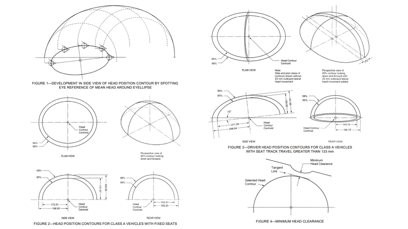
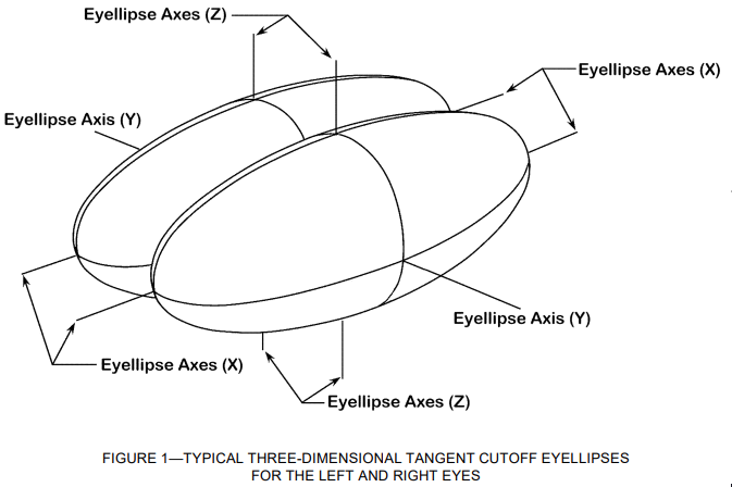
Using Head Position Contours in Design—When applying head position contours in design, the following considerations should be noted. These contours represent typical head locations for a population, not specific individuals. In this document, the contours for Class A vehicles are based on a U.S. population with an equal mix of males and females. The contours are created by applying a mean head profile (from SAE Paper 750356) to the relevant tangent cutoff eyellipse. (See Figure 1.) This means that a plane drawn tangent to the surface of a 95th percentile head contour will contain 95% of the population’s head locations on one side of the plane, with 5% on the other side. However, this does not mean that 95% of head locations are enclosed within the contour.
The surface of a head position contour reflects the outer surface of heads, including hair. If the top of a 95th percentile contour just touches a vehicle surface, it indicates that 5% of the population (split equally between males and females) would have their head or hair in contact with that surface when seated in their preferred posture. Designers should account for additional clearance to ensure occupants’ heads or hair do not touch vehicle surfaces or structures during normal driving or riding postures.
Selecting the Correct Head Position Contour
Three key factors influence which head contour should be used: seat track travel length (TL23), desired accommodation percentile, and the occupant’s seat location.
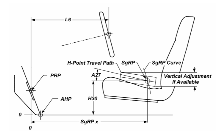
- Seat Track Travel (TL23)—The size and position of the head contour depend on the fore/aft seat track travel. There are three categories: 0 mm (fixed seat), up to 133 mm, and greater than 133 mm. Seat track travel also affects the side view angle of the contour. For adjustable seats (with any seat travel), the head contour is tilted 12 degrees downward in the front. Fixed seats do not have this tilt.
- Accommodation Percentile Values—Head contours are available for 95th and 99th percentiles, with the 99th percentile contour being larger. The 95th percentile contours are typically required for the dimensions defined in SAE J1100.
- Occupant Seat Location—For the driver and front outboard passenger, the head contours are 23 mm wider in rear view than for other seats, with the extra width located on the outboard side of the occupant’s centerline. There are six possible head contours for these positions, depending on seat track travel and the desired accommodation percentile. For center occupants in the front row, the adjustable seat head contour is used, but without the 23 mm extra width.
For other seat locations, only two fixed seat head contours are available: 95th and 99th percentiles. For rear seats with adjustable fore/aft travel or back angle, there are currently no data to create specific head contours. Until such data become available, the fixed seat head contour should be used.
Head Position Contour Geometry
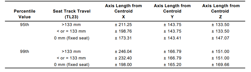
Head Position Contour Geometry—Head position contours are created by modifying 3D ellipsoids. The initial ellipsoid’s size is determined by the X, Y, and Z axis lengths, based on the desired accommodation percentile and seat track travel. The centroid of the ellipsoid serves as the reference point for positioning the final head contour.
The final contour’s size and shape vary depending on the accommodation percentile, seat track travel, and the occupant’s seat location.
Final Steps—Divide the contour along the lateral (Y) center plane while keeping the centroid aligned with the inboard section. Create a 23 mm wide lateral segment along the x,z curve of the ellipsoid and place it in the middle of the divided contour. The inboard edge of this segment aligns with the ellipsoid centroid. Final dimensions for the 95th and 99th percentile contours are in Tables 2 and 3.
Constructing an Ellipsoid—Use the values from Table 1 to construct the appropriate ellipsoid and identify its centroid. This point will remain fixed during contour creation.
Discarding the Lower Half—For all contours, the lower half of the ellipsoid is discarded, and the centroid becomes the base of the final contour. (This step completes the contours for fixed seat rear passengers, as shown in Figure 2.)
Extending the Contour for Driver and Front Row Passengers—For drivers and front-row outboard passengers, the contour is asymmetrical in the rear view, extending 23 mm farther on the outboard side. The ellipsoid centroid will no longer be centered within the final contour.
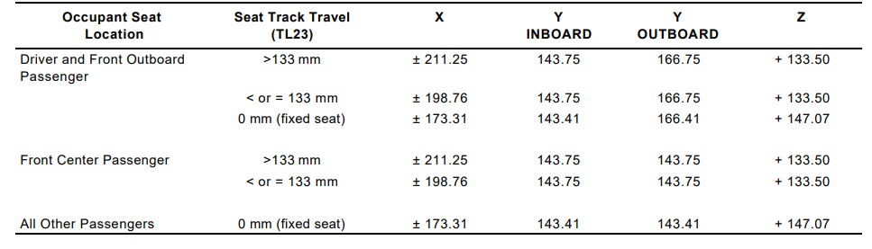
ELLIPSOID CENTROID TO OUTER EDGE OF THE HEAD POSITION CONTOUR (mm)
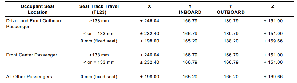
ELLIPSOID CENTROID TO OUTER EDGE OF THE HEAD POSITION CONTOUR (mm)
Locating Head Position Contours in Class A Vehicles
Locating Head Position Contours in Class A Vehicles—Head position contours can be positioned either relative to the cyclopean eyellipse centroid or directly from the vehicle grid. The contour’s location in relation to the eyellipse centroid is determined solely by the amount of seat track travel. In all cases, the ellipsoid’s centroid aligns with the y-coordinate of the cyclopean eyellipse centroid, which matches the SgRP y-coordinate (W20, occupant centerline).
Locating from Vehicle Grid—Alternatively, the head contours can be positioned directly using the vehicle grid without referencing the cyclopean eyellipse centroid. The corresponding equations are provided in Table 5.
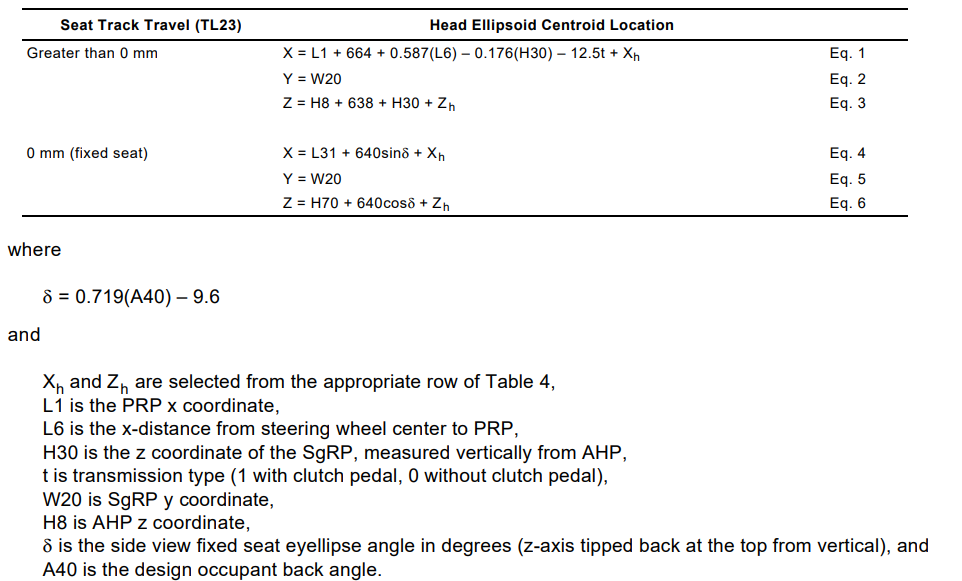
Locating from Cyclopean Eyellipse Centroid—To position the head contour, adjust the ellipsoid’s centroid in X, Y, and Z space based on the values in Table 4, relative to the cyclopean eyellipse centroid.
Assessing Head Clearance
Head clearance is defined as the shortest distance between the head position contour and any interior surface or protrusion, measured at a 90-degree angle from the contour (see Figure 4). To ensure that the vehicle accommodates the percentage of occupants represented by a given percentile head position contour, sufficient space must exist between the contour and the vehicle’s interior surfaces. Without this clearance, some occupants may have their head or hair come into contact with the vehicle’s interior.
The head clearance dimensions outlined in SAE J1100 are based on sections cut perpendicular to the grid through the ellipsoid centroid of the head contour, viewed from the side and rear.

I like gathering useful information , this post has got me even more info! .